1350 × 600 mm Full Field Panel
The full panel spans six 225 mm modules and eight 75 mm courses. Its 1350 × 600 mm gross face area is 0.81 m².
PU Faux-Brick Wall Panels with Matching Corners
The molded polyurethane body carries a terracotta-brick appearance and recessed light mortar lines. The panel has an 8 mm backing base with up to 17 mm face relief, totaling 25 mm at the highest points.
Brick faces follow a 225 × 75 mm module with 10 mm mortar-line spacing. Alternating half-brick starts establish the running bond across the face.
The flat panels use rectangular perimeter edges. Separate half panels and L-shaped outside corners continue the same brick scale, course spacing and decorative face reference.

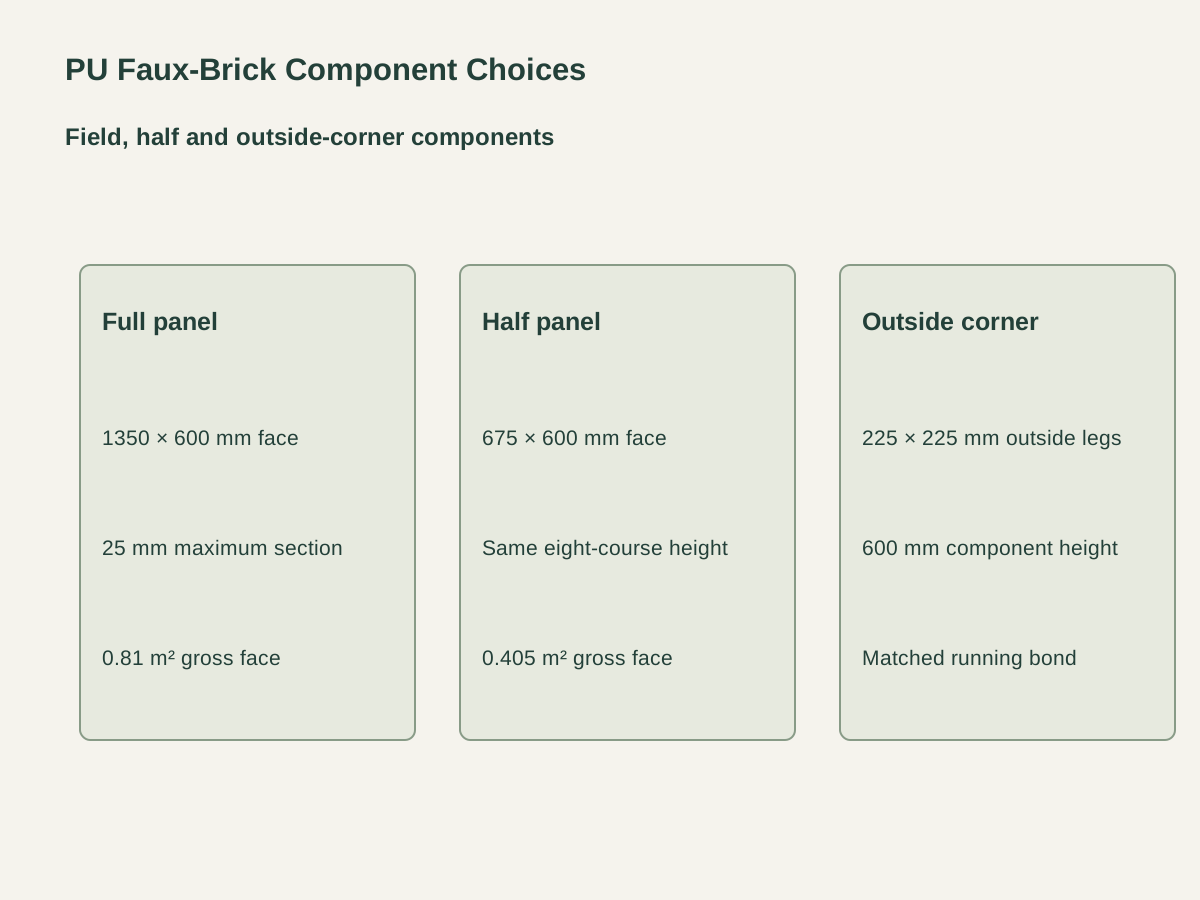
The full panel spans six 225 mm modules and eight 75 mm courses. Its 1350 × 600 mm gross face area is 0.81 m².
The half-width panel spans three brick modules across the same eight courses. Its 0.405 m² gross face supports planned end runs and shorter wall sections.
The corner component returns 225 mm along each outside face at 600 mm height. Its two exposed legs align with the flat-panel courses around the corner.
| Panel material | Molded polyurethane with terracotta-brick decorative face |
|---|---|
| Panel component | 1350 × 600 × 25 max mm · 0.81 m² gross face |
| Backing and relief | 8 mm base + up to 17 mm face relief = 25 mm maximum |
| Brick and mortar module | 215 × 65 mm faces; 225 × 75 mm module; 10 mm mortar lines |
| Full-panel layout | Six modules across × eight courses; 0.81 m² gross face |
| Half and outside corner | 675 × 600 mm half panel; 225 × 225 × 600 mm outside corner |
| Wall interface | Course alignment, substrate, adhesive/fixings, seams and exposed ends on wall drawing |
| Supply unit | Individual full, half and outside-corner components with scheduled fixing and seam materials |
 Open product drawing ↗
The wall elevation keeps the 75 mm course pitch continuous across full, half and corner components. Cuts and end pieces retain the running-bond start and the chosen mortar-line appearance.
The mounting schedule sets substrate preparation, compatible adhesive and any mechanical fixing locations. Openings, penetrations, exposed ends and supporting surfaces are identified on the same wall drawing.
The takeoff records full and half panels by face and corners by vertical run. Panel cuts, seam treatment, finish touch-up and retained spares receive their own component quantities.
Count 1350 × 600 mm full panels and 675 × 600 mm half panels by wall elevation. Gross panel area supports the takeoff while cuts and site openings remain on the actual layout.
List the 225 × 225 × 600 mm corner components by handed wall junction and vertical run. Edge terminations and special cut pieces remain distinct from flat field quantities.
Schedule adhesive, mechanical fixings where used, seam treatment and matching surface touch-up. Wall preparation and installation work receive assigned responsibilities.
Protect raised brick faces and corner tips in transit. Elevation labels identify components, decorative references, spare quantities and destination.
The panel is molded polyurethane with a terracotta-brick decorative face over an 8 mm base. Face relief rises up to 17 mm, giving a 25 mm maximum overall section.
Each 215 × 65 mm brick face follows a 225 × 75 mm module with 10 mm mortar lines. Alternate courses start with half-brick ends to form running bond.
The full panel measures 1350 × 600 mm, spanning six modules across and eight courses high. Its gross face area is 0.81 m².
Choose a 675 × 600 mm half panel or a 225 × 225 × 600 mm outside corner alongside the full field panels. Half-panel gross face area is 0.405 m².
The wall elevation carries the 75 mm course pitch across flat panels and corners. It identifies starts, end cuts, seam treatment and exposed edges against the chosen running-bond arrangement.
Include wall elevations, component counts, openings, corners and decorative sample. Add the supporting substrate, fixing/seam package, installation responsibility, spare quantities, protection and destination.
 600 × 1200 mm PU Mushroom-Stone Wall Panel
 GFRC Limestone-Look Wall Panels with Cast Back Ribs
 600 × 1200 mm PU Pyramid-Relief Wall Panels
 600 × 1200 mm PU Mountain-Rock Wall Panel