Open Paper Bay
The main layout keeps one full-width open bay above the lower cupboard. The 160 mm clear height accepts a defined paper stack or printer accessory arrangement.
Mobile Printer Cabinets with Paper Storage
White high-pressure laminate faces an 18 mm plywood case. Exposed plywood edges and dark pulls give the top, shelf, sides and lower doors a consistent material reference. A 6 mm rear panel carries the cable opening.
The top measures 800 × 600 mm. Below it, the main open bay provides 764 W × 560 D × 160 H mm clear paper space above a fixed shelf and a two-door lower cupboard.
Four locking caster assemblies use 75 mm wheels and a 100 mm installed height. The 650 mm cabinet case plus the caster assemblies establishes the 750 mm overall height.

The main layout keeps one full-width open bay above the lower cupboard. The 160 mm clear height accepts a defined paper stack or printer accessory arrangement.
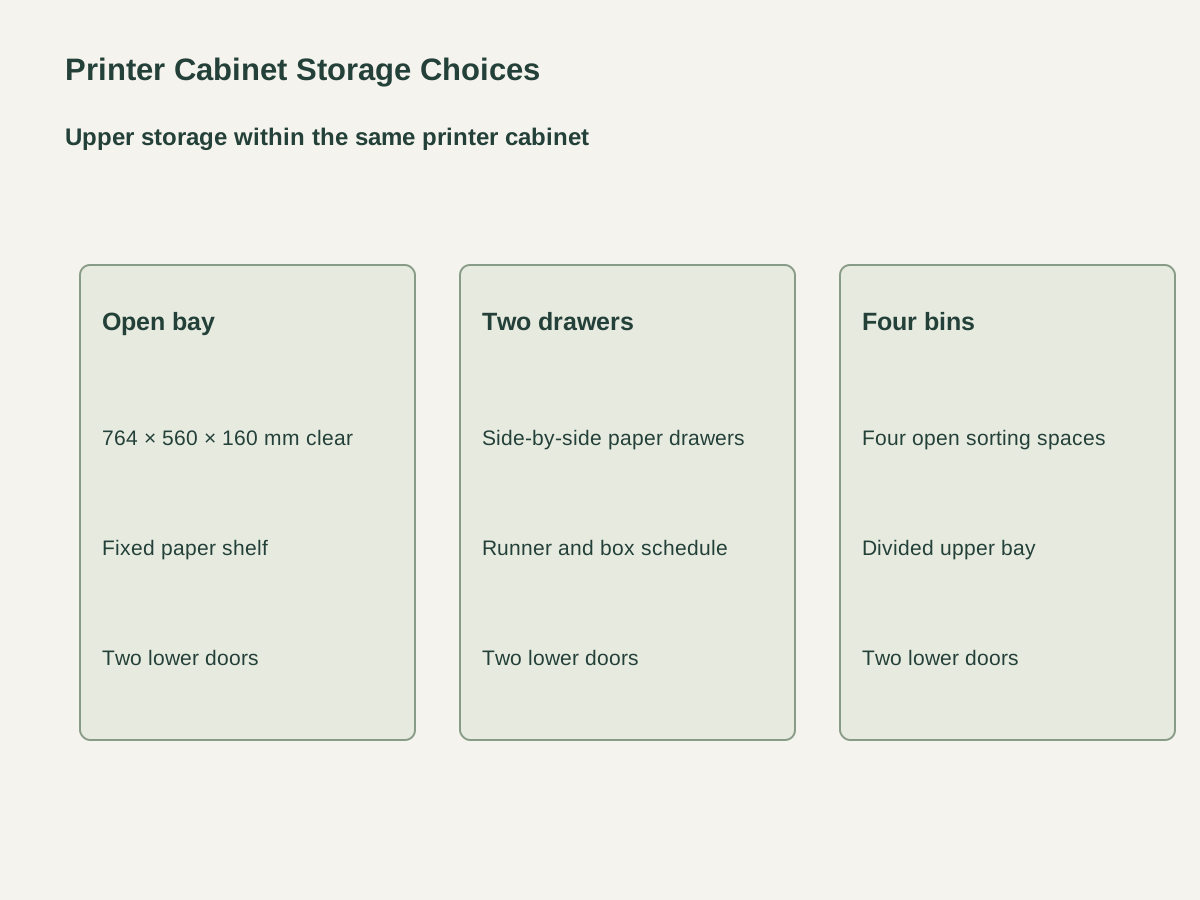
Two side-by-side drawers replace the open bay within the same upper zone. Their fronts, runners, usable depth and paper orientation are coordinated with the 18 mm case.
A divided upper bay forms four open paper bins. The vertical dividers and shelf remain within the same outer 800 × 600 × 750 mm envelope and retain the two-door lower cupboard.
| Case material | 18 mm white HPL-faced plywood; 6 mm back |
|---|---|
| Upper paper-storage layout | 800 × 600 × 750 mm · one 764 × 560 × 160 mm clear upper bay |
| Overall dimensions | 800 W × 600 D × 750 H mm |
| Main open-bay clearance | 764 W × 560 D × 160 H mm |
| Vertical case stack | 18 top + 160 bay + 18 shelf + 436 lower + 18 bottom = 650 mm |
| Caster assembly | Four locking casters; Ø75 mm wheels; 100 mm installed height |
| Printer and cable interface | Full 800 × 600 mm top and coordinated rear cable opening |
| Supply unit | One cabinet with chosen upper storage, two lower doors and four locking casters |
 Open product drawing ↗
Place the actual printer footprint on the 800 × 600 mm top. The equipment schedule locates paper feeds, output trays, lid travel, ventilation and the space used for cartridge access.
The rear cable opening aligns with the printer cord and wall outlet. Cables retain slack for the intended cabinet movement and follow the caster travel route.
The lower cupboard provides a 436 mm clear-height basis. Caster plates, fasteners and locks are detailed with the base panel and the actual equipment/storage load in the order drawing.
Count complete 800 × 600 × 750 mm units by room and choose the open bay, two drawers or four bins. Upper storage components are listed with the matching cabinet.
Schedule the 18 mm white HPL-faced plywood, 6 mm back, door fronts, exposed-edge treatment and dark pulls. Include the rear opening position and size on the case drawing.
List four locking 75 mm-wheel casters per unit, their 100 mm installed height, fixing plates and door hardware. Drawer configurations also list the runner set and drawer construction.
Mark the cabinet by room and printer reference. Protect the laminate faces, pulls and casters for delivery, with unit counts and receiving access on the packing schedule.
The configuration is 800 W × 600 D × 750 H mm. The 650 mm-high case stands on caster assemblies with a 100 mm installed height.
The main bay provides 764 mm clear width, 560 mm clear depth and 160 mm clear height. A fixed 18 mm shelf separates it from the lower cupboard.
Choose one open bay, two side-by-side paper drawers or four open sorting bins. Each layout retains the common case envelope and two lower doors.
The unit uses four locking casters with 75 mm wheels and a 100 mm installed height. Their fixing plates and fasteners are coordinated with the base panel and the equipment load.
The printer sits on the full 800 × 600 mm top, with its footprint, paper trays and service access on the equipment schedule. A rear opening routes the cable toward the outlet.
One unit includes the HPL-faced plywood case, chosen upper storage, two lower doors, pulls and four locking casters. The order also identifies the cable opening, hardware and room label.
 Built-In Home Office Cabinets with a Stone Worktop
 Built-In Hanging-File Drawer Cabinet
 Office Archive Cabinet with Closed Storage and Two Open Niches
 Custom Breakroom Sink & Appliance Cabinet System