Stainless Steel U-Channels for Interior Glass Edges

A brushed stainless U-channel provides a three-sided perimeter detail for decorative fixed glass. Compare a 2400 mm straight bar with a bar-and-gasket package, using a selected 20 × 25 mm section, 17 mm nominal clear width and 12 mm glass fitting target.

Channel form
Open three-sided U section with equal-height legs and connecting base
Stainless U-Channel Package
304 brushed stainless · 20 × 25 mm outside section · 1.5 mm nominal wall · 2400 mm length
Nominal metal wall and clear width
1.5 mm metal wall · 17 mm nominal clear width
Stainless U-Channel Package U-Channel Straight Bar

Three-Sided Stainless U-Channel with a Brushed Face

20 × 25 mm U Section

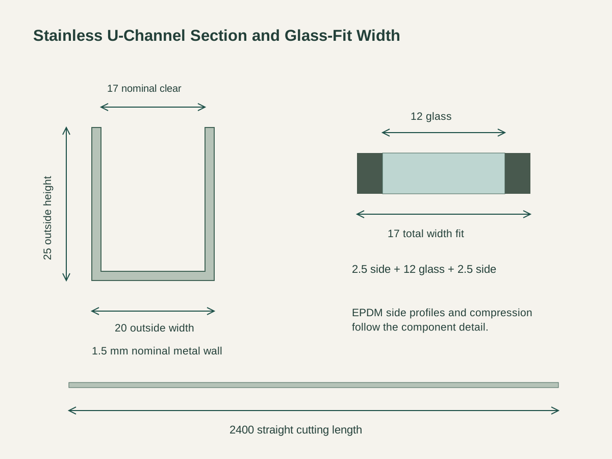
The selected channel has two equal-height upright legs joined by a flat base. Its outside section is 20 mm wide and 25 mm high, with a nominal 1.5 mm metal wall. The open side receives the selected glass-edge and side-gasket detail.

304 Stainless with a Brushed Finish

The selected material is grade 304 stainless steel with a brushed silver surface. The component schedule identifies grain direction, formed corners, cut ends and exposed joint treatment. Straight bars are supplied to the selected 2400 mm cutting basis.

17 mm Nominal Clear Width

The two 1.5 mm side walls leave a nominal 17 mm space across the 20 mm outside width. A 12 mm glass target and two 2.5 mm side-gasket targets complete that width-fit schedule. Gasket compression, tolerances and retained edge details are coordinated with the selected components.

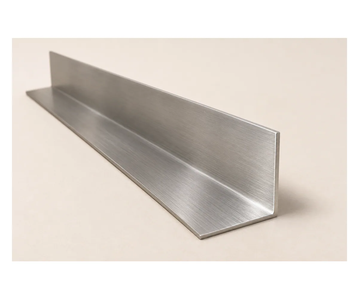
Complete straight brushed stainless U-channel with equal upright sides, connecting base, open top and both cut ends shown.

Straight Channel and EPDM Side-Gasket Packages

Complete brushed stainless U-channel with comparison of bar-only and EPDM side-gasket supply packages.

U-Channel Straight Bar

The base package supplies the 2400 mm brushed stainless channel. It establishes the selected three-sided section for a glass edge coordinated with the glazing. End caps, cut lengths, joints and attachments remain named entries in the project component schedule.
Channel with EPDM Side Gaskets

The alternate package adds selected EPDM gaskets at both sides of the glass. Each side has a 2.5 mm fitting target beside the 12 mm glass target. The gasket profile and compression detail are matched to the chosen glass edge and channel.

Matched Brushed Edges and Ends

Both packages retain the same grade and brushed silver appearance. Exposed ends, corner cuts and joining lines are coordinated by run. The order distinguishes the stainless finish reference from the gasket material and profile, chosen on their own.

Stainless Glass-Edge Channel Dimensions

Channel formOpen three-sided U section with equal-height legs and connecting base
Component package304 brushed stainless · 20 × 25 mm outside section · 1.5 mm nominal wall · 2400 mm length
Outside section20 W × 25 H mm
Nominal metal wall and clear width1.5 mm metal wall · 17 mm nominal clear width
Selected material and finishGrade 304 stainless steel · brushed silver
Glass and side fitting targets12 mm glass + two 2.5 mm EPDM side-gasket fitting targets
Straight bar length2400 mm selected cutting basis
Supply unitOne selected straight channel bar, with side gaskets where chosen and scheduled caps/cuts/attachments
20 × 25 mm U section with 1.5 mm wall and 17 mm clear width, separate 12 plus 2.5 plus 2.5 mm width-fit diagram and 2400 mm cutting length. Open product drawing ↗

Glass Edge Fit, End Details and Support Attachments

Decorative Fixed-Glass Perimeter

Use the channel on the scheduled interior fixed-glass perimeter detail. The project drawing identifies glass dimensions, retained edge depth, channel location and surrounding finishes. The glass support and channel attachment are coordinated with that complete assembly.

Fitting Width and Component Tolerances

The selected nominal fit is 12 mm glass plus 2.5 mm at each side within the 17 mm clear channel. Record the actual glass tolerance and selected gasket profile together. The component detail establishes the gasket compression and insertion arrangement.

Runs, Corners and End Closures

The 2400 mm bar length provides the cutting basis for straight runs. Identify finished lengths, miters, exposed ends and end caps on the location schedule. Joints, attachment access and adjoining glass panels are coordinated before the cut list is finalized.

Stainless U-Channel and Gasket Supply

Stainless Channel Bars

List the required 2400 mm bars with the selected 20 × 25 mm outside section and nominal 1.5 mm wall. Include grade 304, brushed surface direction and the chosen finish reference.

Selected EPDM Side Gaskets

For the gasket package, list the selected side profiles and quantities. Keep the 12 mm glass target, 2.5 mm side fitting targets and component tolerance schedule with that item reference.

Cuts, Caps and Attachments

Schedule finished cuts, corner miters, end caps and joining details individually. Channel fixings and glass support components are named with the supporting substrate and assembly detail.

Location Labels and Protection

Group bars and gasket lengths by opening or glass-panel reference. Protect the brushed faces and cut ends, with matching caps and fixing components identified in the same packing list.

Stainless Glass-Edge Channel Order Contents

Channel
20 × 25 mm U section, 1.5 mm nominal wall and 2400 mm bar length
Gasket fit
12 mm glass target, selected EPDM side profiles and fitting tolerances
Project detail
Retained edge, glass support, end caps, cuts, joints and channel attachments
Delivery
Opening references, quantities, finish protection and matched component packing

Stainless Steel Glass-Edge U-Channel Questions

What is the selected U-channel section?

It is an open three-sided section, 20 mm wide and 25 mm high outside. Two equal upright legs connect to the base. The selected nominal stainless wall is 1.5 mm, leaving 17 mm nominal clear width between the side walls.

How is the glass fitting width calculated?

The selected target combines 12 mm glass with a 2.5 mm side-gasket allowance at each face. Together these total 17 mm. The actual gasket profile, compression and glass tolerances are coordinated in the component fitting detail.

What changes in the gasket package?

Both packages use the same brushed 304 stainless channel. The alternate adds selected EPDM side gaskets, with their profile and fitting schedule matched to the glass edge and the 17 mm nominal clear channel width.

How are straight lengths and corners ordered?

The selected bar length is 2400 mm. The location schedule lists finished cuts, miters, joints, exposed ends and end caps, with quantities and allowances attached to each run.

What determines glass support and channel attachment?

The complete project assembly identifies glass size and retained edge depth, supporting construction and attachment positions. The selected glass support, channel fixings and substrate are coordinated on that same drawing.

What should the quotation include?

Provide channel run lengths, the chosen package, glass thickness and edge detail. Add supporting substrate, caps, corners, joints, selected finish, quantities and opening labels for coordinated delivery.

Request a Stainless Glass-Edge Channel Quote

Complete straight brushed stainless U-channel with equal upright sides, connecting base, open top and both cut ends shown.
Stainless Steel U-Channels for Interior Glass EdgesU-Channel Straight Bar
sales@novarmia.com
Stainless Steel U-Channels for Interior Glass EdgesRequest a Quote