600 mm Straight Border Strip
The main 600 × 100 × 10 mm strip carries one centered brass line along its full length. The line meets the short edges at the 100 mm border centerline.
Marble Floor Border Inlays with Flush Brass Lines
Honed white natural marble forms the border body: a straight 100 mm-wide strip with finished edges and a stone-face range kept consistent across adjoining pieces.
A 6 mm-wide, 3 mm-thick brass insert sits flush in a 3 mm-deep machined channel, so the 10 mm marble body keeps 7 mm of stone below the inlay and the walking face stays level.
Corner and T modules carry the same line width into the required edges. Their brass meeting points, stone faces and module orientations follow the border layout and piece numbers.
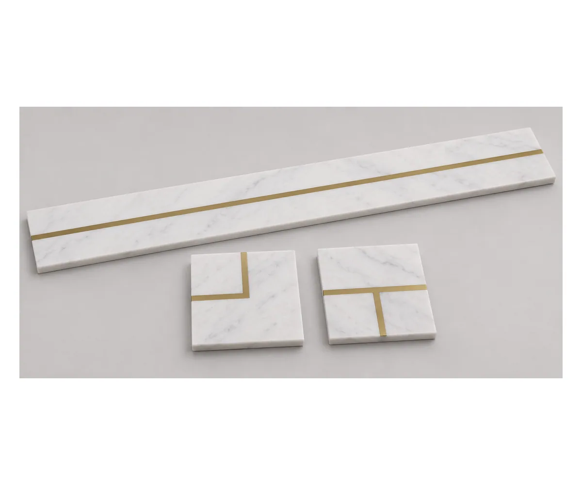
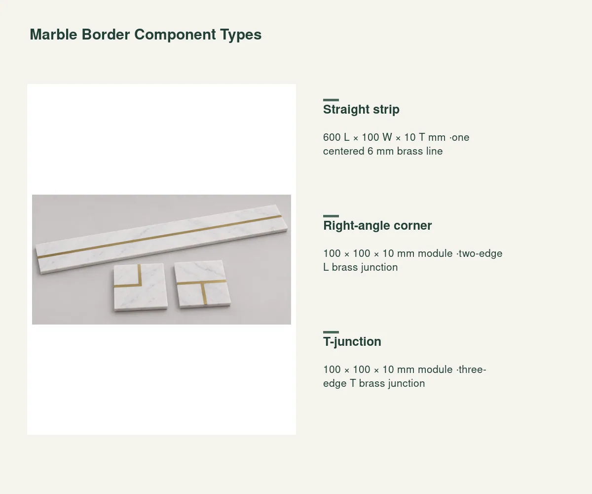
The main 600 × 100 × 10 mm strip carries one centered brass line along its full length. The line meets the short edges at the 100 mm border centerline.
The 100 × 100 mm corner module joins two adjacent edge midpoints through the center. Rotating the piece turns the same border line around the required room corner.
The 100 mm-square T module connects three edge midpoints. Its orientation is assigned on the floor plan where one border branch meets a continuous run.
| Stone body | Honed white natural marble; 10 mm total thickness |
|---|---|
| Border component | 600 L × 100 W × 10 T mm ·one centered 6 mm brass line |
| Straight format | 600 L × 100 W × 10 T mm |
| Junction formats | 100 × 100 × 10 mm; right-angle corner or T |
| Brass insert | 6 W × 3 T mm; flush with stone |
| Machined channel | 3 mm deep; 7 mm marble remains below |
| Pattern interface | Centered line reaches assigned edge midpoints; orientation by border plan |
| Supply unit | One numbered straight, corner or T component with face/joint schedule |
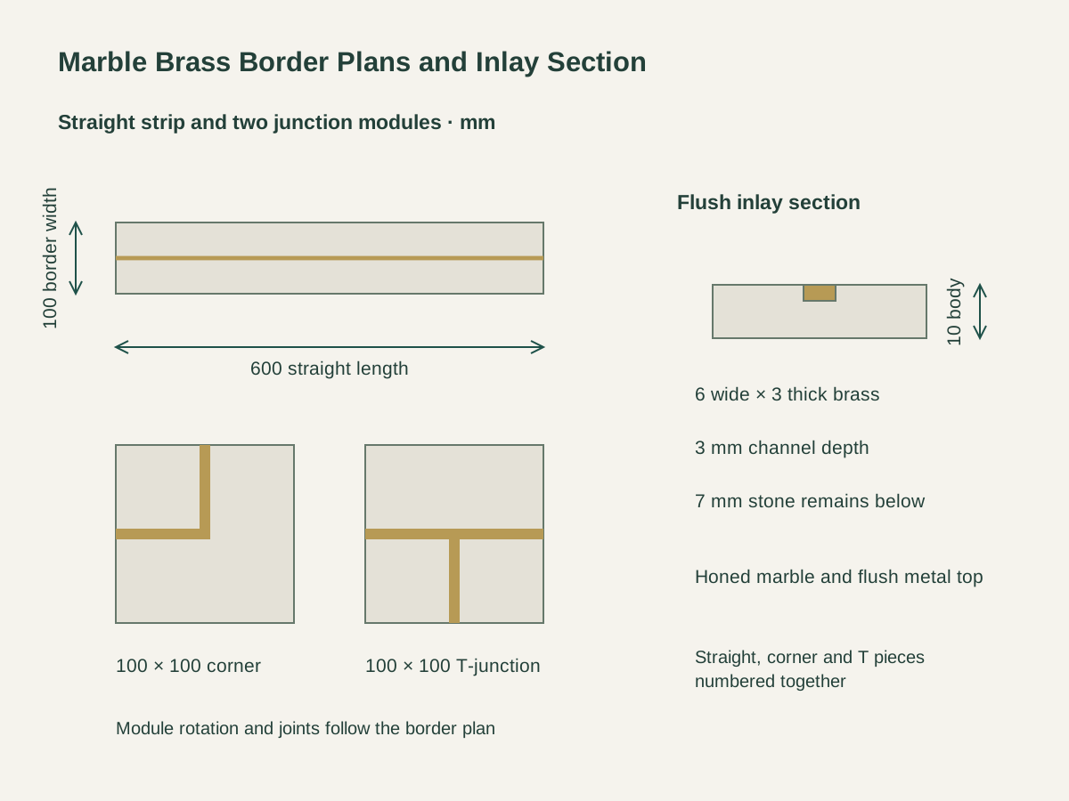 Open product drawing ↗
The floor drawing places straight runs, corners, T branches and end pieces, with module orientation and line direction taken from that one layout so the brass line meets each adjoining edge correctly.
The surrounding floor, setting bed and border top are detailed together. The brass remains flush with the stone, with the selected joints and movement interfaces carried through the border assembly.
The order records the marble face range, brass appearance, channel fit and bonding system. Edge finishing, metal/stone interfaces and the intended floor use are kept on the same component schedule.
Take off 600 mm strips, 100 mm corners and T pieces as three counts, and record branch orientation, cut ends and spare components by room and border run.
Quote 10 mm marble, 6 × 3 mm brass inserts and 3 mm-deep channels. Include the flush face finish, meeting points and exposed-edge lengths for each component type.
Schedule setting materials, component joints, finished levels and movement details against the adjacent floor. Surface and installation documentation follows the actual project use and complete material assembly.
Protect the stone corners and brass faces in packing. Mark straight/corner/T parts by layout number, with component counts, spares and destination on the crate list.
The 3 mm-thick insert sits in a 3 mm-deep channel. Its top aligns with the stone face, while 7 mm of the 10 mm marble body remains below the channel.
The straight strip is 600 mm long, 100 mm wide and 10 mm thick. One 6 mm brass line runs down its center and reaches both short edges.
A 100 mm-square corner connects two adjacent edge midpoints through the center. Its rotation on the floor plan determines which way the border turns.
The 100 mm-square T piece joins a branch to a continuing line. Its three connected edge midpoints match the same 6 mm brass centerline as the straight and corner components.
The floor detail carries the 10 mm component, setting bed and adjacent finished level together. Joint widths, movement interfaces and bonding references are assigned to the complete stone/metal floor assembly.
Count 600 mm strips, 100 mm corners and 100 mm T pieces one by one against the layout, then add cut ends and spares by component type, with piece numbers and orientation on the packing list.
 Marble Basketweave Mosaics with Dark Stone Dots
 Circular Waterjet Marble Floor Medallion
 Tumbled Travertine Square Mosaic Tiles
 Honed White & Gray Marble Herringbone Mosaic