304 Stainless Steel with a Brushed Finish
The 304 brushed option keeps a directional satin appearance across the tube, returns and brackets. Specify one finish reference for all exposed parts, including the treatment of welds and end connections.
Returned Stainless Steel Wall-Mounted Handrail
A continuous round grip follows the wall, with both ends returning toward the wall face. The selected tube has a 42.4 mm outside diameter and 2 mm wall. End returns and their weld finishing form part of the rail assembly.
The selected section leaves 50 mm clear between the tube surface and wall. Three intermediate saddle brackets support the 2000 mm run. Bracket position, returned-end attachments and wall fixings are coordinated as one matched assembly.
This component provides a wall-side grip. It does not fill an open stair edge or replace a guardrail. Stair pitch, grip height, wall construction and attachment loads belong to the project mounting detail.

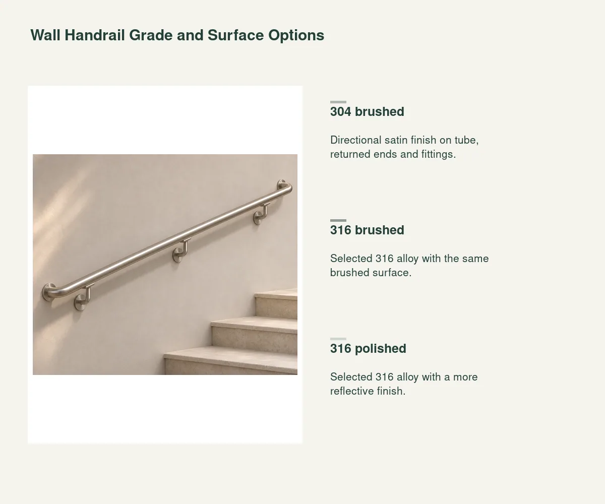
The 304 brushed option keeps a directional satin appearance across the tube, returns and brackets. Specify one finish reference for all exposed parts, including the treatment of welds and end connections.
The 316 brushed option changes the selected alloy while retaining the same round grip and satin finish. Keep the grade on the tube and fitting schedule.
The polished option has a more reflective surface on the same selected rail geometry. Review a finished connection as well as a straight tube sample, because weld blending and bracket surfaces remain on show after installation.
| Component | Round wall handrail with returned ends |
|---|---|
| Grade and finish | 304 stainless steel · brushed finish |
| Selected tube | 42.4 mm outside diameter × 2 mm wall |
| Selected run length | 2000 mm finished length along the run |
| Selected wall gap | 50 mm clear from tube surface to finished wall |
| Intermediate supports | 3 saddle brackets for the selected run; final attachment design by project |
| End treatment | 2 returned ends, with exposed connections finished to the selected surface |
| Supply boundary | Rail and scheduled fittings; wall structure, load design and installation each agreed for the project |
| Standards & certificates | Matched to the ordered model: tell us the standards or certificates your market or project requires, and we confirm in writing which documents are available for this configuration before you order. |
 Open product drawing ↗
Use the finished rail length along the stair or corridor run, with the start, end and any slope change shown on the elevation. The selected straight run is 2000 mm; longer routes need their own joints or continuous-piece schedule.
Locate the three intermediate brackets against the actual masonry, concrete or framed-wall backing. The bracket count is a selected arrangement. Anchor type, embedment and any additional supports are established for the wall and project loads.
Show the returned ends and 50 mm tube-to-wall gap in section. Check trim, door movement and changes in wall finish before setting the rail line. Mark the handrail height from the finished walking surface on the project elevation.
Compare quotations with the same 304 or 316 grade, 42.4 mm tube, 2 mm selected wall and finished run length. A price for loose tubing does not include a finished returned-end handrail.
Count the two end returns, three intermediate saddles and any end attachment plates. List weld blending and the brushed or polished finish so the quoted assembly matches the intended exposed detail.
Identify any included fixing hardware as its own line next to the rail and brackets. Wall preparation, structural backing, anchor selection and site installation are included only when expressly listed.
Label each rail by floor, wall and run reference, then keep matching brackets and finishes together. The order schedule includes quantities, protective packing, destination and delivery stage, with spares on their own line.
It is a wall-mounted handrail. An open stair edge needs a separate guardrail design and infill. Specify the wall grip and open-edge protection as distinct assemblies.
The selected alloy changes while the round grip geometry stays the same. Keep the grade on the material schedule for the tube, returns and fittings.
The selected 50 mm is the clear distance from the nearest tube surface to the finished wall. It is separate from the bracket projection measured to the tube centerline.
Three intermediate saddles are included in the selected 2000 mm arrangement. Wall backing, fasteners and project loads determine the final attachment design.
Specify the finished length along the sloping run and show the angle, start and end on the elevation. Changes of direction or pitch need their own connection details.
List each finished run, grade, finish, returns, brackets, mounting wall and destination. Identify fixing hardware, backing and installation individually, so a loose tube price is never compared with a finished assembly.
 Frameless Glass Railing with Point Fixings and a Metal Handrail
 Stainless Steel Cable Railing with Square Posts and a Flat Top Rail
 Solid Oak Oval Wall Handrails with Metal Brackets
 Vertical-Bar Steel Railing Panels with Square Posts