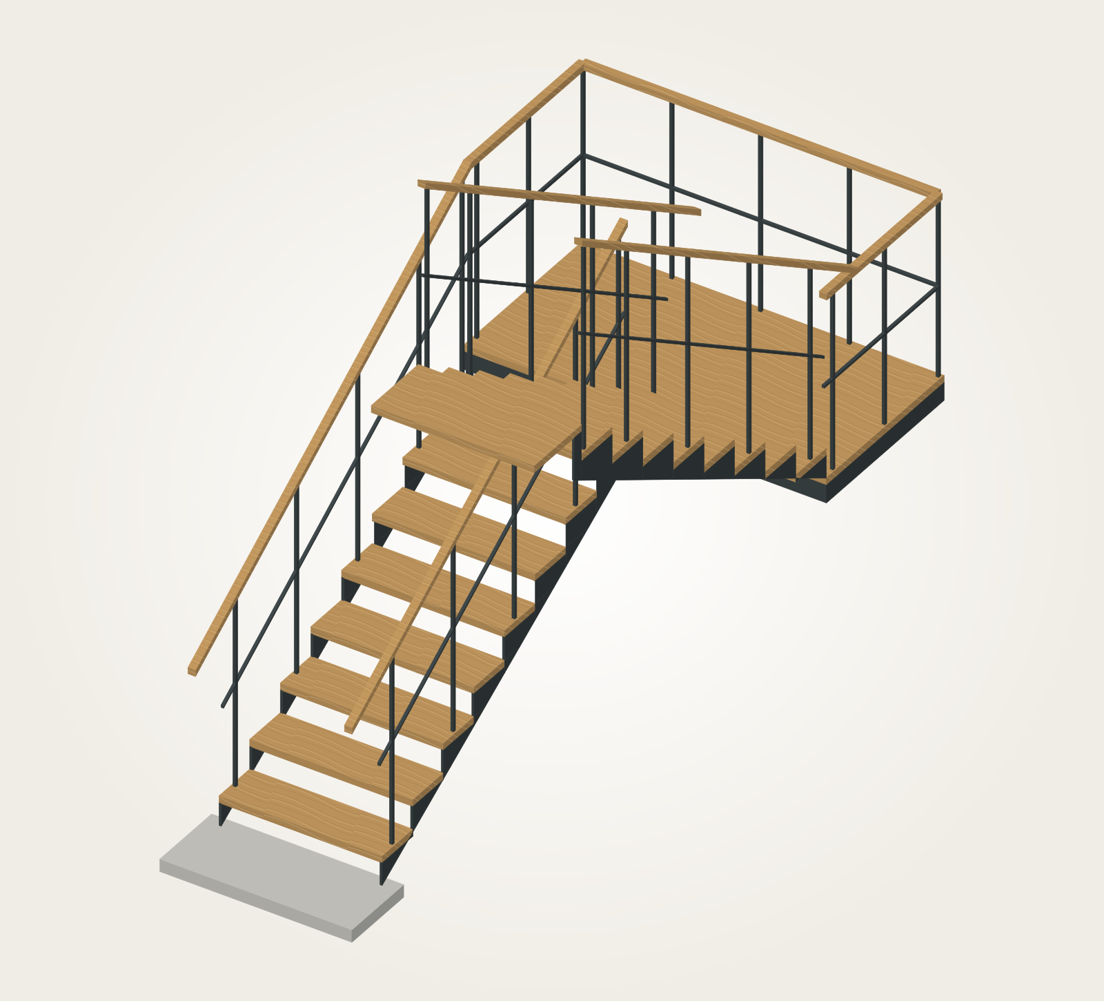
3000 mm Main Floor Rise
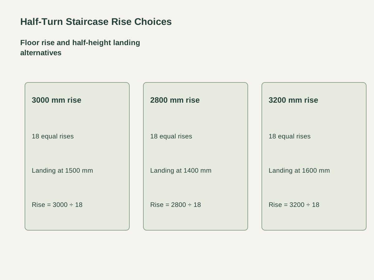
The main layout divides 3000 mm into eighteen equal rises, about 166.7 mm each. Nine rises reach the 1500 mm landing; the next nine reach the upper floor.
Half-Turn Staircase Layout
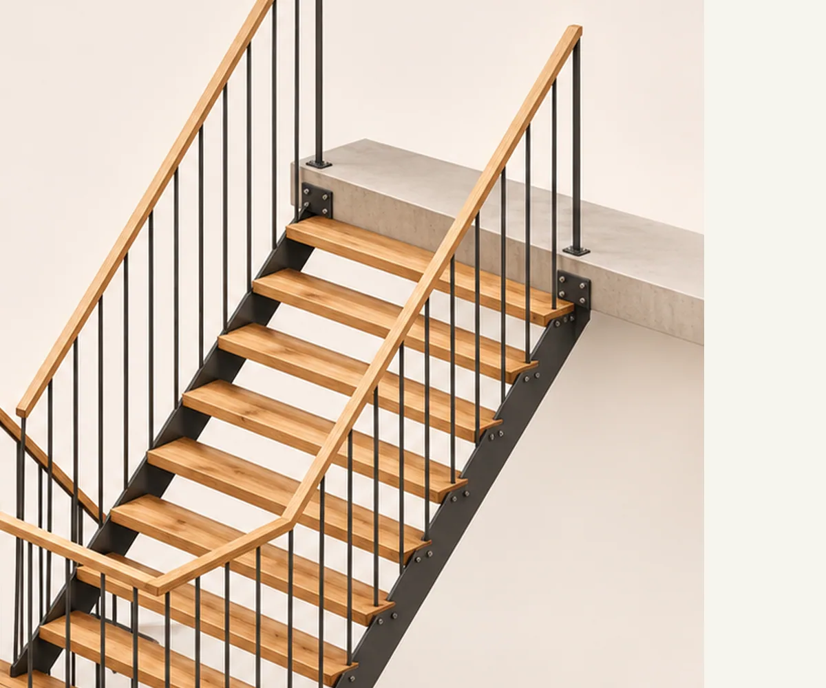
Each straight flight carries its treads between two carbon-steel side plates. The steel finish, tread brackets and connections remain tied to the engineered staircase assembly.
Eight separate treads form each flight, giving sixteen individual 900 W × 260 going × 40 T mm oak treads. The open-riser arrangement and exposed wood edges remain part of the selected staircase appearance.
A 2000 × 1000 mm rear landing joins the two flights through a 180° turn. The package coordinates its oak landing surface, steel support, vertical-bar guards and oak handrails with both flights and floor arrivals.
The main layout divides 3000 mm into eighteen equal rises, about 166.7 mm each. Nine rises reach the 1500 mm landing; the next nine reach the upper floor.
The lower-rise configuration retains eighteen rises, about 155.6 mm each, and places the landing at 1400 mm. The tread widths, 260 mm goings and half-turn plan remain the same design basis.
The higher-rise configuration uses eighteen rises, about 177.8 mm each, with the landing at 1600 mm. Floor/head connections and the guard geometry follow that complete elevation.
| Stair construction | Two parallel steel-side-stringer flights with open oak treads and half-turn landing |
|---|---|
| Floor-to-floor rise | 3000 mm floor rise · 18 rises · approximately 166.7 mm each |
| Default rise and landing | 3000/18 mm exact rise basis; nine rises to the 1500 mm landing |
| Oak treads | 16 separate treads; each 900 W × 260 going × 40 T mm |
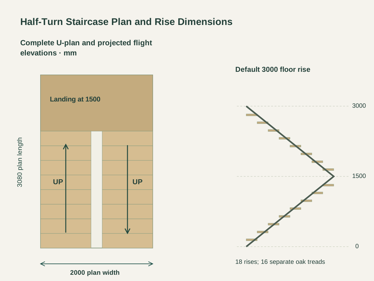
| Flight run and landing | Eight 260 mm goings per flight = 2080 mm run; landing 2000 × 1000 mm |
| Plan module | 2000 W × 3080 L mm; 200 mm central well between tread-width zones |
| Engineering and guards | Side plates, brackets, beams, anchors, guard dimensions and handrails coordinated with actual opening |
| Supply unit | Two-flight stair set with four side stringers, 16 treads, landing, guard/handrail and engineered connection schedule |
 Open product drawing ↗
The lower flight rises away from the entrance toward the rear landing. The upper flight returns in the opposite plan direction toward the upper arrival, with a 200 mm central well between the 900 mm tread-width zones.
Each flight has eight 260 mm goings, giving a 2080 mm plan run. Adding the 1000 mm landing depth forms a 3080 mm plan module; the structural opening detail adds supports, projecting fixings, guard space and the required clear passage/headroom.
The structural schedule sets side-plate sections, brackets, landing beams, floor anchors and head connections against the actual building. Guard/handrail dimensions, fixing access and installation sequence are coordinated with that same stair opening.
Quote the 2800, 3000 or 3200 mm floor rise with the eighteen-rise layout. Opening references retain the U-plan, landing elevation and number of staircase sets.
List four side stringers, tread supports, landing steelwork and the engineered connection package. Finish references, site interfaces and fabrication/assembly responsibilities stay with those structural components.
Schedule sixteen oak treads, the landing surface, vertical steel bars, posts and oak handrails. Wood finish, nosing/edge details and the full guard layout remain tied to the assembled stair.
Label flight, tread, landing and guard parts by opening and assembly position. Protection, actual piece weights, receiving/lifting access and the installation sequence follow the delivery schedule.
The lower flight rises toward the rear landing. The upper parallel flight leaves that landing in the opposite direction, returning toward the upper arrival through a 180° change in route.
Choose 2800, 3000 or 3200 mm floor-to-floor rise. All three use eighteen equal rises, giving approximately 155.6, 166.7 or 177.8 mm per rise respectively.
Each flight uses eight individual oak treads before the landing or upper floor, giving sixteen treads in total. Nine rises per flight include the rise onto that landing or floor.
The oak treads are 900 mm wide, have 260 mm goings and are 40 mm thick. The rear landing is 2000 × 1000 mm, with eight goings giving a 2080 mm plan run per flight.
The opening/structural detail coordinates floor levels, plan space, headroom, clear passage and supporting construction. It defines the steel sections, landing beams, anchors, head connections and complete guard arrangement.
Include floor-to-floor levels, opening/floor sections, the chosen rise and room plan. Add tread/steel finishes, support and guard requirements, installation sequence, actual-piece handling, access and destination.
 Galvanized Grating Access Steps with Top Platforms
 Closed-Riser Timber Staircase with a Quarter-Turn Landing
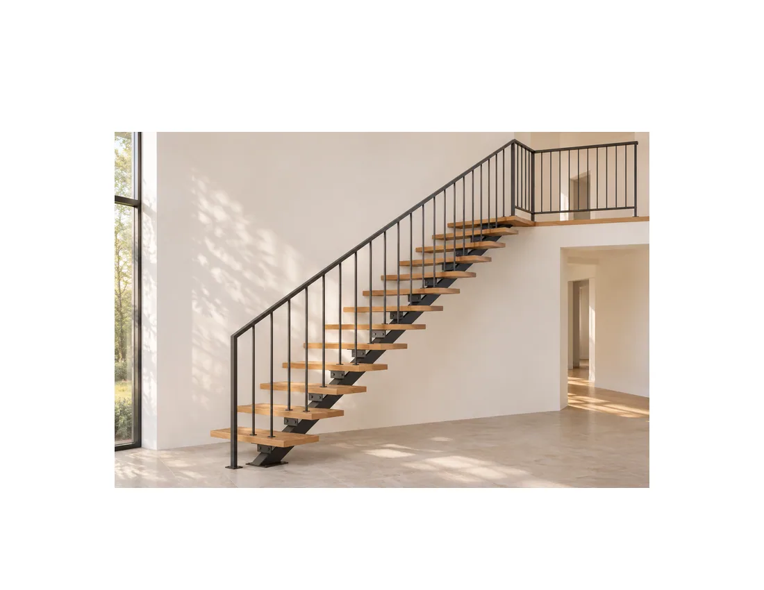 Straight Mono-Stringer Staircase with Hardwood Treads
 Custom Steel Spiral Staircase with Center Support