Three Rises to 525 mm
The main module has two ordinary treads and one top platform. Two 250 mm goings plus the 500 mm platform give a 1000 mm horizontal grating-run length.
Galvanized Grating Access Steps with Top Platforms
The access module uses numbered carbon-steel stringer/frame components with a galvanized finish. The fabrication schedule identifies member sections, connections, endplates and the corresponding site attachments.
The main module has two 900 mm-wide grating treads with 250 mm goings, followed by a 900 × 500 mm top platform. Its three 175 mm rises place that platform 525 mm above the lower floor.
A 40 mm round top rail follows each side of the step run and platform. The height basis is 900 mm vertically above the tread-nose line and platform surface, with post and connection details carried on the fabrication drawing.


The main module has two ordinary treads and one top platform. Two 250 mm goings plus the 500 mm platform give a 1000 mm horizontal grating-run length.
The four-rise option adds a third ordinary tread before the platform. Three 250 mm goings plus 500 mm give a 1250 mm run, with the same 900 mm tread width.
The five-rise option uses four ordinary treads and the same 500 mm-deep top platform. Its 1500 mm run and 875 mm platform height are coordinated with the upper landing.
| Frame and walking surfaces | Galvanized carbon-steel bolt-up frame; open steel-bar grating treads/platform |
|---|---|
| Access-step module | 3 × 175 =525 H mm ·2 treads +500 mm platform ·1000 mm run |
| Uniform rise and going | 175 mm rise; 250 mm going per ordinary tread |
| Walking-surface width | 900 mm tread and platform width |
| Top platform | 900 W × 500 D mm; 525/700/875 mm above lower floor |
| Run and tread count | 1000/1250/1500 mm run; 2/3/4 ordinary treads plus one platform |
| Side-rail basis | Two 40 mm round top-rail runs; 900 mm height above tread-nose line/platform |
| Supply unit | One numbered module: frame, treads, platform, side rails and bolt/endplate schedule |
 Open product drawing ↗
The site drawing establishes the lower-floor datum, upper landing and chosen module height. It also locates the platform interface, approach area, doors and surrounding clearances.
The fabrication package assigns member sections, grating support, bolt groups, baseplates, endplates and site attachments to the actual installation. Supporting substrates and the required engineering criteria travel with those details.
The order records grating bar orientation, edge treatment, post positions and side-rail connections. The project review establishes the guard arrangement, openings, applicable use criteria and required loading documentation.
Quote three-, four- or five-rise modules by landing reference. Carry the platform height, 900 mm tread width, 250 mm going and total grating-run length together.
List stringers, frame members, treads, top platforms and their matched fixing locations. Grating specification, member sections and galvanized-finish requirements use the fabrication schedule.
Count both side-rail runs, posts, connection plates, bolt sets and site attachments. The upper landing and lower substrate details identify the corresponding fixing assemblies.
Bundle numbered components with the bolt/endplate schedule and landing reference. Protect galvanized surfaces and grating edges, and retain component counts and destination on the packing list.
The three-rise module contains two ordinary grating treads and one deeper top platform. The three walking levels are 175, 350 and 525 mm above the lower floor.
Each ordinary tread contributes 250 mm of going, and the top platform contributes 500 mm. Two treads plus the platform give 1000 mm; three give 1250 mm; four give 1500 mm.
The top platform is 900 mm wide and 500 mm deep. Its height is 525, 700 or 875 mm for the three-, four- or five-rise module respectively.
The two side runs use 40 mm round top rails with a 900 mm vertical height basis above the tread-nose line and platform surface. Posts and connections follow the module fabrication detail.
The fabrication package assigns member sections, grating support, bolt groups, endplates, baseplates and anchor details to the actual landing and supporting substrates. The project criteria and engineering documentation use that same assembly.
One module includes the numbered stringer/frame components, ordinary treads, top platform, two side-rail runs and bolt/endplate schedule. Component labels and the landing reference organize packing and assembly.
 Closed-Riser Timber Staircase with a Quarter-Turn Landing
 Custom Steel Spiral Staircase with Center Support
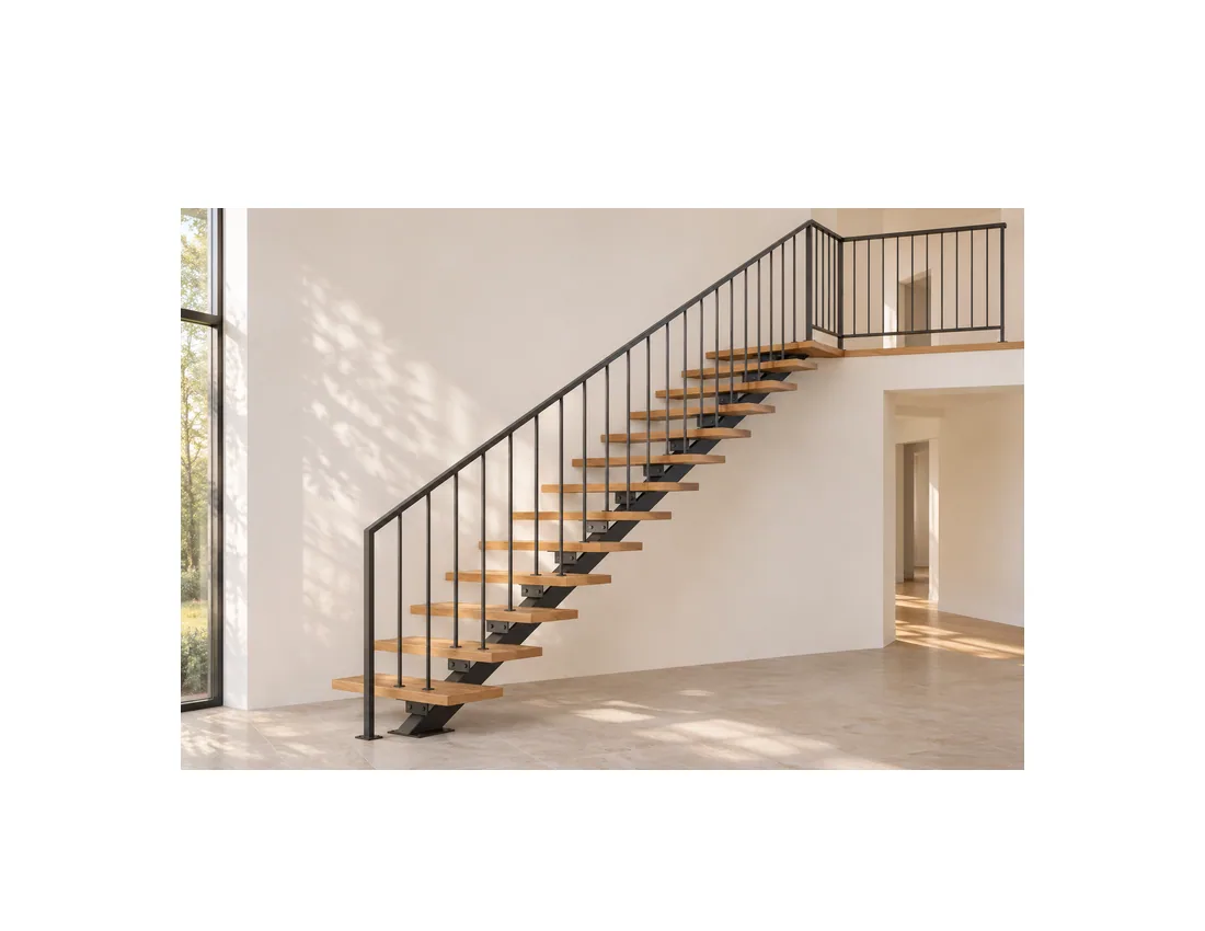 Straight Mono-Stringer Staircase with Hardwood Treads
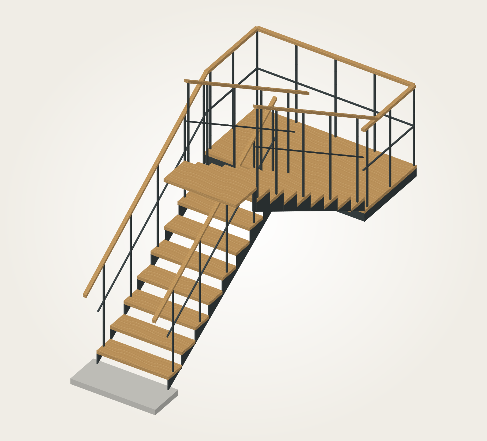 Half-Turn Twin-Stringer Steel Staircase with Oak Treads