800 mm Modules and 1740 mm Legs
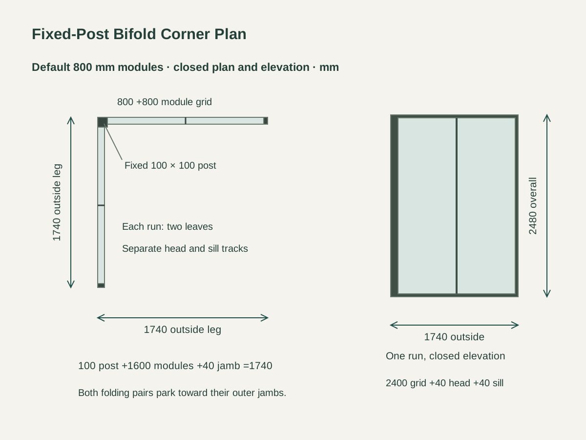
The main plan combines a 100 mm post, two 800 mm nominal leaf modules and a 40 mm outer jamb along each leg. Each outside leg measures 1740 mm, with a 2480 mm overall frame height.
Fixed-Post Corner Bifold Glass Door Sets
Each perpendicular run contains two equal glazed leaves linked as a folding pair. Each pair folds toward its own outer jamb, while the opposite run has its own track and operating hardware.
A fixed 100 × 100 mm square post remains at the 90-degree intersection. It connects the two perimeter frames and gives both tracks and jamb seals a defined corner termination.
The configuration uses 70 mm thermally broken aluminum leaf profiles with charcoal powder-coated faces. The glazing build is 6 mm glass, 12 mm sealed airspace and 6 mm glass, coordinated with glazing support and safety requirements.


The main plan combines a 100 mm post, two 800 mm nominal leaf modules and a 40 mm outer jamb along each leg. Each outside leg measures 1740 mm, with a 2480 mm overall frame height.
Two 700 mm modules reduce each outside leg to 1540 mm. The corner-post section, outer jamb and overall height remain the same, with the narrower folding pairs on their respective tracks.
Two 900 mm modules increase each outside leg to 1940 mm. The takeoff includes the wider glass, leaf members and matched operating hardware for both sides of the corner.
| Door construction | Two perpendicular aluminum bifold runs, with two glazed leaves per run |
|---|---|
| Module and outside-leg size | 2 +2 leaves ·1740 mm outside leg dimensions ·2480 mm overall height |
| Fixed corner post | 100 × 100 mm square; permanent 90-degree intersection |
| Overall height | 2480 mm =40 head +2400 module grid +40 sill |
| Leaf profiles | 70 mm thermally broken aluminum; charcoal powder coat |
| Insulating glass build | 6 mm glass +12 mm sealed airspace +6 mm glass =24 mm |
| Operating layout | Two pairs fold toward separate outer jambs; two track/sill sets |
| Supply unit | One corner opening: four leaves, one post, two frames and itemized hardware |
 Open product drawing ↗
The plan identifies the permanent post, two head tracks, two sills and the two outer jambs. Structural supports, post fixings and perimeter anchorage are coordinated as one L-shaped opening.
Each pair parks at its outer jamb, leaving the corner post clear. The door schedule records folding direction, stack envelope, handle clearance and usable passage from the final hardware geometry.
Both sills meet the fixed corner-post detail. Floor levels, drainage, threshold joints, glazing support and weather seals follow the project opening and glazing schedule.
Specify 700, 800 or 900 mm modules for both legs, and list the four leaves and permanent 100 mm post together. Mark the two legs and their outer jambs on the opening number.
Include 70 mm thermally broken profiles, the charcoal finish and the 6/12/6 glass build, with glass safety requirements, face references and member fabrication on the order.
Schedule separate head/sill runs, folding hinges, carriers or rollers, guides, pulls, locks and seals for each pair. Post connections and outer-jamb fixings receive their own detail references.
Label leaves by run and sequence. Protect glass edges and metal faces, and pack the post, tracks, sills and hardware with a matching component list for the destination opening.
There are four glazed leaves, two on each perpendicular run. Each run forms its own two-leaf folding pair and operates on its own head and sill arrangement.
Yes. A permanent 100 × 100 mm square post sits at the 90-degree intersection. Both door runs terminate at that post and fold toward their respective outer jambs.
Add the 100 mm corner post, two nominal leaf modules and the 40 mm outer jamb. The 700, 800 and 900 mm modules produce 1540, 1740 and 1940 mm outside legs respectively.
The selected leaf profiles are 70 mm thermally broken aluminum with a charcoal finish. The insulating-glass build is 6/12/6 mm, with glass safety and support requirements carried on the opening schedule.
Each pair parks at the outer end of its own run. The final operating-hardware detail defines the parked stack, handle clearance and resulting clear passage for both sides.
The L-shaped opening plan establishes structural supports, post and frame anchors, floor and sill levels, drainage, glazing requirements and stack space. The two track runs and corner connections are supplied to that coordinated detail.
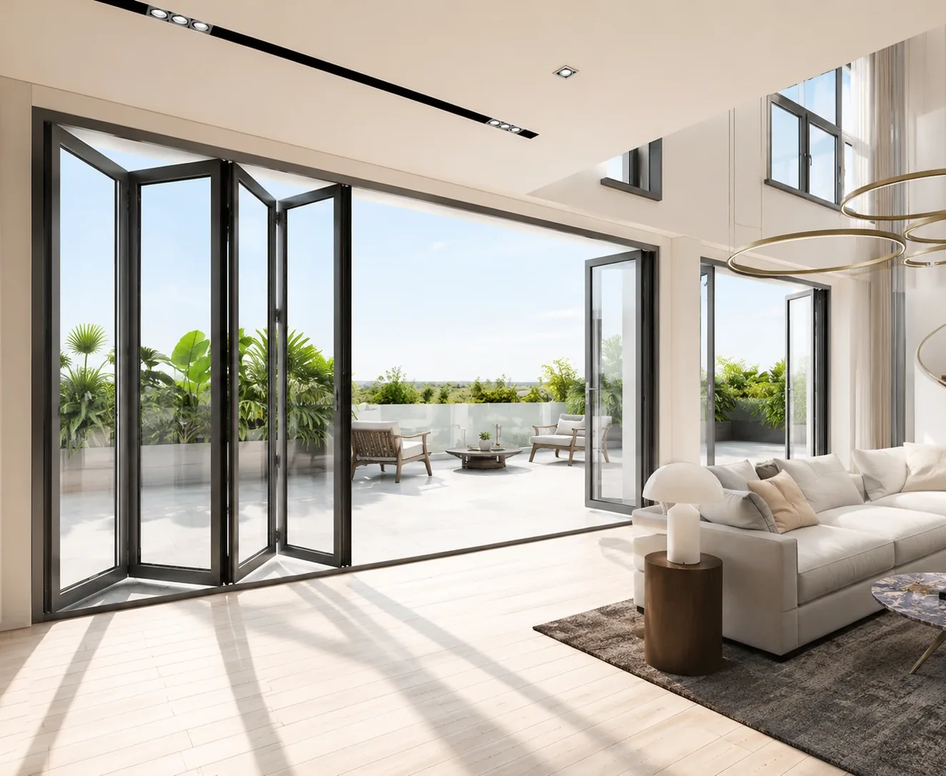 68 Series Thermal Break Aluminum Folding Glass Door
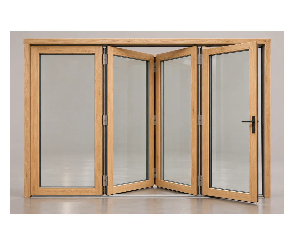 Oak-Clad Aluminum Folding Glass Patio Doors
 Six-Panel Aluminum Bifold Patio Door
 Four-Leaf Bifold Patio Doors with a Traffic Door