800 mm Width with Ten Fins
Ten 40 mm faces and nine 40 mm gaps sit between two 20 mm margins. The narrower assembly keeps the same 120 mm depth and 2400 mm overall height.
Floor-to-Ceiling Solid-Oak Fin Dividers
Each vertical fin has a 40 mm-wide face and 100 mm depth, with the natural-oak grain and clear matte finish carried around every face and edge.
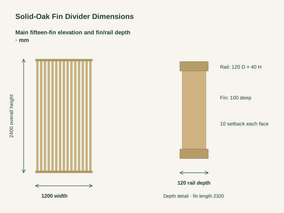
The main 1200 mm assembly uses fifteen fins and fourteen 40 mm gaps, with 20 mm edge margins. The repeated open spaces allow views between rooms while the deep fins define the divider plane.
Top and bottom rails are 120 mm deep and 40 mm high. Their 2400 mm overall assembly leaves 2320 mm-long fins between them, with each 100 mm-deep fin centered to give a 10 mm setback from either rail face.

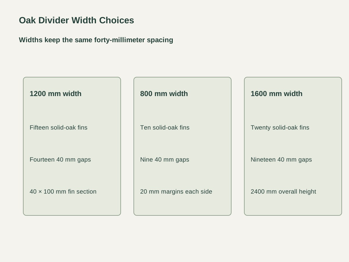
Ten 40 mm faces and nine 40 mm gaps sit between two 20 mm margins. The narrower assembly keeps the same 120 mm depth and 2400 mm overall height.
The main assembly totals 600 mm of fin faces, 560 mm of gaps and 40 mm of margins. It preserves one regular 80 mm fin-and-gap rhythm across the divider.
Twenty fins and nineteen gaps extend the same spacing across 1600 mm. The floor and head rails follow the full width of the assembly.
| Timber and finish | Solid oak with clear matte finish |
|---|---|
| Assembly width and fin count | 1200 W × 120 D × 2400 H mm · fifteen fins with 40 mm gaps |
| Overall height and depth | 2400 H × 120 D mm |
| Fin section and length | 40 mm face × 100 mm depth; 2320 mm length |
| Clear gap and margins | 40 mm between fins; 20 mm at each side |
| Floor and head rails | 120 D × 40 H mm; fins centered with 10 mm face setbacks |
| Main width equation | 15 × 40 + 14 × 40 + 2 × 20 = 1200 mm |
| Supply unit | One width-defined fin assembly with two continuous rails and scheduled connections |
 Open product drawing ↗
The order drawing locates the rail faces against finished floor level and the supporting ceiling or head structure. Rail anchors and connection access follow the actual substrates.
Keep the 120 mm rail depth and fin projection on the room plan, and coordinate adjacent door swings, skirting, casework and lighting with the open gaps and rail ends.
An assembly elevation establishes the grain direction, fin count and end margins. Clear finish, exposed-edge treatment and timber matching use the same physical sample reference across the run.
Count 800/10, 1200/15 or 1600/20 width/fin assemblies by location. Each uses 2400 mm height, 120 mm rail depth and the common fin section.
Schedule the 40 × 100 mm fins, 120 × 40 mm rails and clear matte finish, including the grain reference, rail ends and edge treatment.
Itemize fin-to-rail joints, floor/head connections and substrate-specific anchors. Connection access and any installation sequencing follow the project detail.
Identify assemblies and rails by room/run. Protect fin edges and finished faces, with component counts, assembly sequence and destination on the packing list.
Fifteen 40 mm fin faces total 600 mm. Fourteen 40 mm gaps add 560 mm, and two 20 mm side margins add 40 mm, giving 1200 mm overall.
The widths are 800 mm with ten fins, 1200 mm with fifteen fins and 1600 mm with twenty fins. All retain 40 mm faces, 40 mm gaps and 20 mm side margins.
Each fin is 100 mm deep. It is centered within the 120 mm-deep rails, leaving a 10 mm setback from each rail face.
The complete assembly is 2400 mm high. Two 40 mm-high rails leave 2320 mm-long vertical fins between them.
Continuous floor and head rails carry the assembly interfaces. The order detail locates anchors, connection access and supporting substrates against the finished floor and head levels.
One assembly includes the width-defined set of solid-oak fins, full-width floor and head rails, clear matte finish and scheduled connections. Run labels, anchoring details and packing counts follow the project order.
 Concealed Door and Flush Wood Wall-Panel System
 Window Seat Bench with Three Closed Storage Bays
 Wall Bed Millwork with Side Storage
 Custom Reception Counter with a Lowered Service Section