600 mm Straight Coping
The straight piece has square end cuts and a 600 × 300 mm plan outline. Its rounded nose follows the full front edge, with the underside groove continuing along the run.
Rounded-Nose Porcelain Pool Coping Tiles
The coping uses warm-gray through-body porcelain with a matte textured top. Its 600 × 300 mm straight format and 20 mm section define the slab-like pool-edge component.
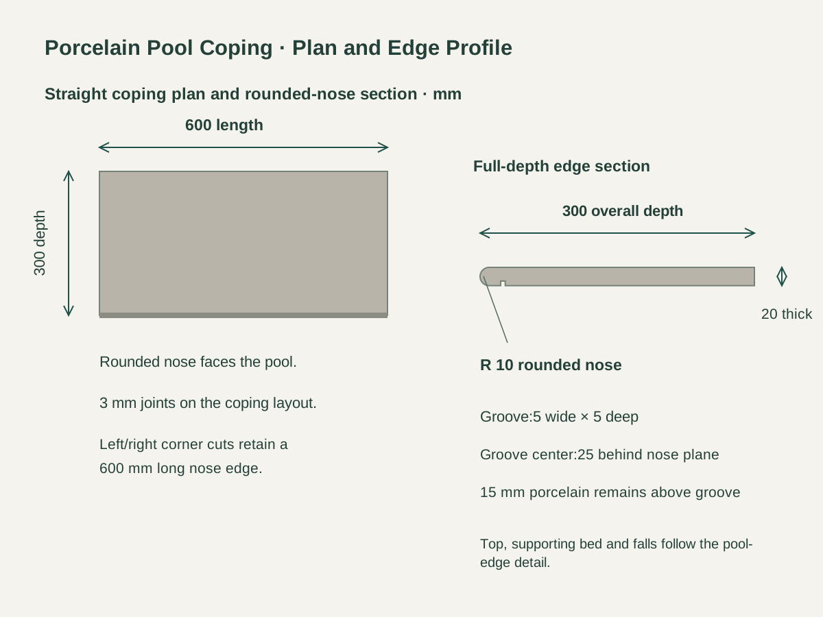
A full rounded nose runs along the 600 mm water-facing edge. The 10 mm radius fits the 20 mm tile thickness, providing the continuous curved front profile shown on the coping section.
A 5 mm-wide,5 mm-deep groove runs parallel to the nose on the underside. Its center is 25 mm back from the foremost nose plane, retaining 15 mm of porcelain above the groove.

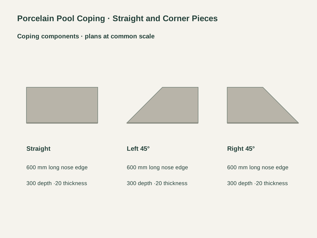
The straight piece has square end cuts and a 600 × 300 mm plan outline. Its rounded nose follows the full front edge, with the underside groove continuing along the run.
The left-hand component retains a 600 mm long nose edge and 300 mm plan depth, with a 45° left end cut. Its shorter rear edge is 300 mm in the defined corner plan.
The mirrored right-hand component uses the same long-edge, depth and thickness dimensions. Left/right labels follow the view facing the rounded nose from the pool side.
| Coping material and face | Through-body warm-gray porcelain; matte textured top |
|---|---|
| Coping component | 600 L × 300 D × 20 T mm · square end cuts |
| Straight plan and section | 600 L × 300 D × 20 T mm |
| Rounded nose | R 10 full rounded profile along the water-facing edge |
| Underside groove | 5 mm wide × 5 mm deep; center 25 mm behind foremost nose plane |
| Handed corner geometry | 45° end cut;600 mm long nose edge and 300 mm shorter rear edge |
| Joint and interface | 3 mm design joints; bearing, falls, movement and waterproofing on edge detail |
| Supply unit | One straight or handed corner coping piece with nose and underside groove |
 Open product drawing ↗
The coping layout identifies the water-facing edge, perimeter runs and corner hands. Straight lengths, shaped ends and opening or access locations are counted from that continuous nose line.
The setting-out plan uses 3 mm clear joints between coping pieces. Corner cuts and course ends are located with those joints, while movement joints follow the complete pool-edge assembly.
The coping section carries the supporting bed, falls, pool-shell edge, adjacent deck and waterproofing interface together. Surface-use and immersion-related documentation is specified for the chosen porcelain and setting system.
List straight, left 45° and right 45° pieces as three counts by pool-edge run, with the nose-line layout, cuts, access positions and spares kept with the takeoff.
Quote the gray textured face, 20 mm section, R 10 nose and 5 × 5 mm underside groove as one fabrication reference, with cut ends and finish continuity matched to that profile.
Itemize bedding, grout, movement joints, bearing and the pool and deck waterproofing interfaces, with site work and the material and assembly documents assigned in the project schedule.
Protect the rounded edges and corner tips with separators and end protection. Labels identify straight/corner hand, pool run, quantity, packed weight and destination.
The straight tile is 600 mm long,300 mm deep and 20 mm thick. A full rounded R 10 nose runs along its water-facing 600 mm edge.
The groove is on the underside, parallel to the rounded nose. It measures 5 × 5 mm, with its center 25 mm behind the foremost nose plane and 15 mm of porcelain above it.
Choose left- or right-hand 45° end cuts. Each retains a 600 mm long nose edge,300 mm plan depth,300 mm shorter rear edge and 20 mm section, with the hand defined from the pool side.
Use 3 mm clear design joints on the straight runs and corner layout. The pool-edge detail also locates movement joints and coordinates the adjoining deck, shell and support assembly.
The project edge detail defines the bearing bed, support widths, falls and waterproofing interfaces around the shell. The porcelain, grout and setting materials are specified together for that pool-edge location.
Send a dimensioned nose-line plan, piece hands and quantities, surface and profile reference and spare pieces, plus setting and support needs, run labels, packing and delivery destination.
 Textured Through-Body Gray Porcelain Pool-Floor Mosaic
 Blue & White Square Glass Pool Mosaic Tiles
 Slotted Porcelain Pool Overflow Grating Tiles
 Blue Porcelain Waterline Tiles with Matching Corner Pieces