250 mm Depth with 180 mm Slots
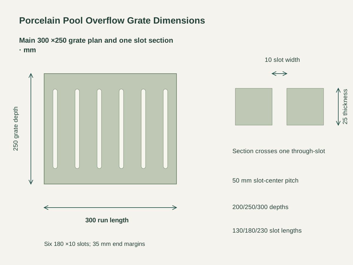
The main grate is 300 L ×250 D ×25 T mm. Its 180 mm slots retain 35 mm solid margins at both depth ends.
Slotted Porcelain Pool Overflow Grating Tiles
The rectangular grate uses textured gray porcelain at a 25 mm thickness requirement. Its solid outer border and finished slot edges follow one accepted ceramic reference.
The main 300 ×250 mm grate has six through-slots, each 10 mm wide and 180 mm long with R5 ends. Their centers repeat at 50 mm pitch along the 300 mm run length.
Each slot leaves 35 mm of solid porcelain at both ends across the grate depth. The removable tile, channel seats and support-bearing arrangement are coordinated as a complete pool-edge assembly.

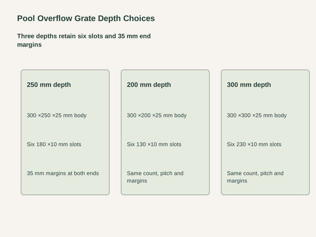
The main grate is 300 L ×250 D ×25 T mm. Its 180 mm slots retain 35 mm solid margins at both depth ends.
The narrower grate retains 300 mm length, 25 mm thickness and six slots. Each slot shortens to 130 mm while preserving the same 35 mm end margins.
The wider grate uses 230 mm-long slots within 300 mm depth. Its slot count, width, pitch and rounded ends remain with the same pattern family.
| Grate material | Textured gray porcelain; 25 mm body requirement |
|---|---|
| Grate depth and slot length | 300 L ×250 D ×25 T mm ·six 180 mm through-slots |
| Common run length | 300 mm |
| Slot pattern | Six through-slots, 10 mm wide with R5 ends |
| Slot-center layout | 25 +50n mm along run length, n=0..5 |
| Solid slot-end margins | 35 mm at both depth ends |
| Pool-edge interface | Support seats, clear span, module joints and removable fit by channel detail |
| Supply unit | One removable grate tile; channel/support components itemized by pool run |
 Open product drawing ↗
The pool detail positions the channel seats, grate bearings and actual clear span. Structural and wet-area requirements are assigned to the final grate/support assembly for the intended pool use.
The channel plan establishes module joints, edge clearance and a lifting route for each tile. Grate seating, adjacent paving and any restraint parts follow that removable access arrangement.
The order identifies channel geometry, drainage connections, grate orientation and accepted textured face. Exposed edges, slot finish and the project surface documentation remain paired with the pool-edge section.
Count 200, 250 or 300 mm-deep modules along the overflow run. Each nominal 300 mm length receives a pool/run reference and the required module-joint detail.
Quote 25 mm porcelain, six 10 mm-wide slots, rounded R5 ends and the matching 130/180/230 mm slot length. The 35 mm end margins stay on the ceramic fabrication drawing.
Schedule support ledges, channel components, grate fit and any specified restraints as separate assembly items. Structural requirements and the actual clear span accompany the grate reference.
Protect long slot mouths, ceramic corners and finished faces. Mark depth, run orientation, module counts and destination on the protected packing list.
Each grate has six rounded through-slots. They are 10 mm wide with R5 ends, and their centers repeat at 50 mm pitch along the 300 mm module length.
The 200, 250 and 300 mm grate depths use 130, 180 and 230 mm-long slots respectively. Each combination leaves 35 mm of solid porcelain at both slot ends.
The main tile is 300 L ×250 D ×25 T mm. Its six slots are 180 mm long within the 250 mm depth.
The pool-edge detail defines support seats, bearing areas and the actual clear span. Required structural and wet-area documentation follows the final grate/support assembly.
The run layout sets module joints, edge clearance and a lifting route. Grate seating, adjacent paving and any restraint detail preserve that planned removal access.
Channel bodies, support ledges, drainage connections and any restraint parts have their own assembly quantities. Grate tiles are labeled by depth, run and orientation, with protected packing and piece counts.
 Blue Porcelain Waterline Tiles with Matching Corner Pieces
 Textured Through-Body Gray Porcelain Pool-Floor Mosaic
 Rounded-Nose Porcelain Pool Coping Tiles
 Blue & White Square Glass Pool Mosaic Tiles