Satin-Silver Aluminum Face
The cover face has a satin-silver aluminum finish requirement. The order reference records the sheen, brushed direction and exposed lips together so adjoining lengths share the same metal appearance.
Aluminum Reducer Strips for Unequal Floor Levels
The cover bridges a small difference between two finished-floor levels with a continuous inclined face. Its 60 mm width overlaps the adjoining surfaces, while the eased lips define the two exposed edges.
A central underside stem engages a separate fixing track within the joint recess. The selected track is 18 mm wide and 10 mm high. Cover and track are supplied as a matched profile set for the chosen level difference.
Three profile choices use the same 60 mm cover width. Each is specified for its 3, 6 or 9 mm finished-floor rise, with the 6 mm version as the default section. The order identifies the required rise on each opening or floor-joint line.
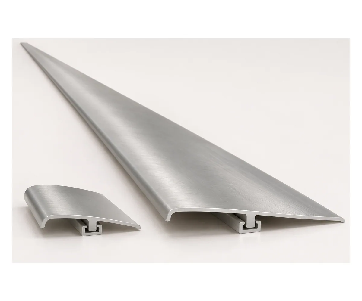
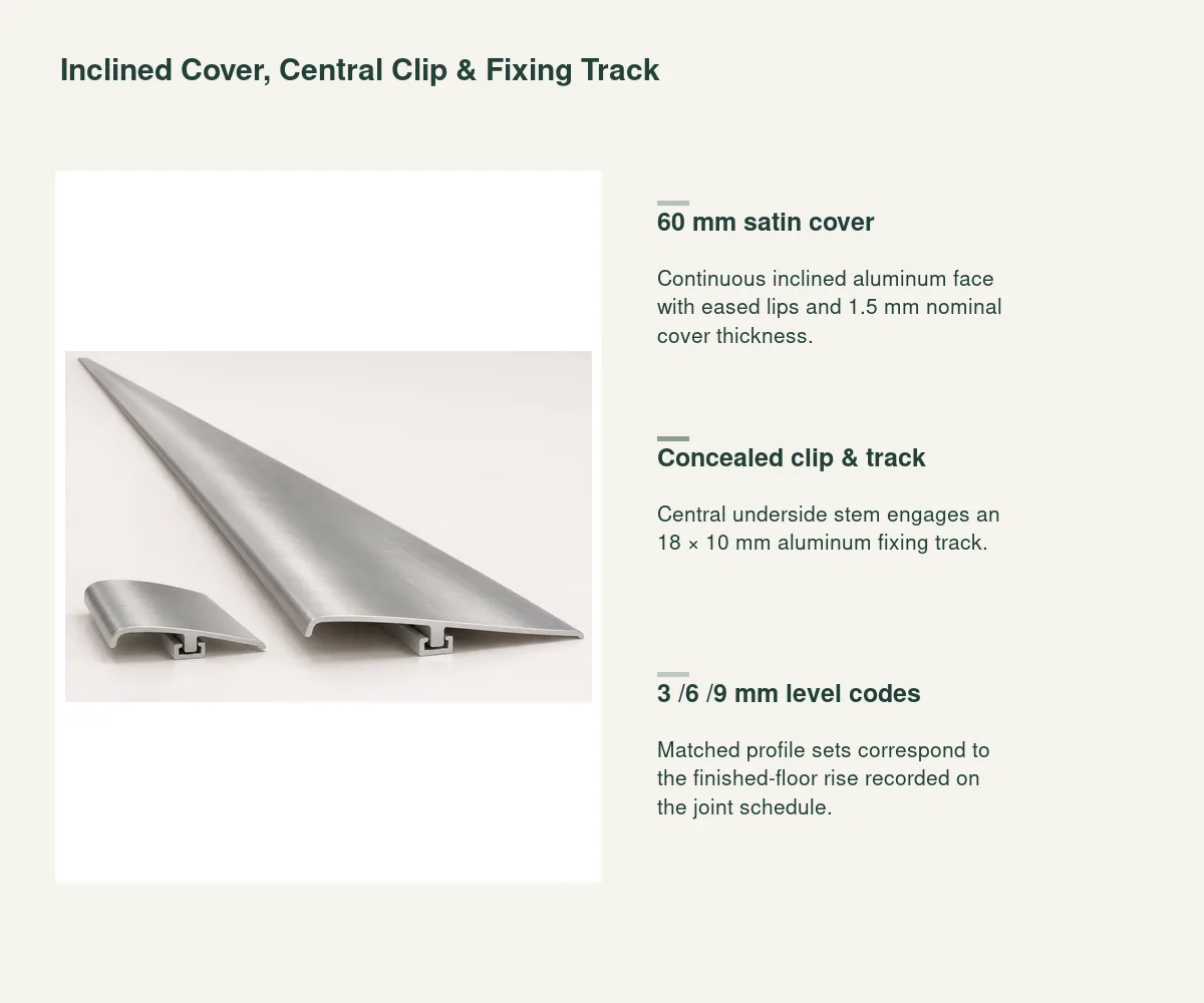
The cover face has a satin-silver aluminum finish requirement. The order reference records the sheen, brushed direction and exposed lips together so adjoining lengths share the same metal appearance.
The cover schedule uses 1.5 mm nominal metal thickness. The inclined face and edge lips are coordinated with the matched clip stem, keeping the exposed profile and hidden fixing connection in one section.
The concealed aluminum track follows the selected cover length and profile code. Track seating and fastener positions are detailed for the supporting substrate within the joint recess.
| Cover width | 60 mm inclined cover. |
|---|---|
| Level difference | 60 mm-wide inclined aluminum cover for a 3 mm finished-level difference; 1.5 mm nominal cover thickness and matched concealed fixing track. |
| Bar length | 2700 mm cover and matched fixing-track length basis. |
| Nominal cover thickness | 1.5 mm aluminum. |
| Fixing track | 18 W × 10 H mm concealed aluminum track with central clip engagement. |
| Joint recess | 20 mm clear width and 12 mm depth below the lower finished-floor datum. |
| Face finish | Satin-silver aluminum with eased exposed lips. |
| Cut schedule | Opening references, finished lengths, 3/6/9 mm rise codes and substrate fixing detail. |
 Open product drawing ↗
The rise is the vertical difference between the completed floor surfaces. Select the 3, 6 or 9 mm profile from those finished datums, then record the adjoining floor materials and the required reducer length.
The selected section reserves a 20 mm clear-width recess with 12 mm depth below the lower finished floor. That space receives the 18 × 10 mm track and its fixing detail while the cover overlaps the adjoining finishes.
Standard bar length is 2700 mm. The joint schedule lists finished cut lengths, opening references, ends and any changes in direction, with each cut assigned to the appropriate rise code and matching track.
The quotation lists the inclined cover and matched fixing track by length and level code. The cut schedule connects those quantities to openings and floor joints, including the selected 3, 6 or 9 mm rise.
The finish covers the satin-silver face and exposed edge lips. The sample section records sheen, metal thickness requirement and the appearance where the cover meets both floor finishes.
The joint detail identifies the substrate and the track-fastening method. Recess preparation and fixing components are listed as their own lines next to the cover/track extrusion lengths.
Protective packing keeps the satin face and lips apart in transit. Labels identify opening, cut length, rise code and matched track, supporting an orderly room-by-room installation sequence.
They are the vertical differences between the two finished-floor surfaces. Each option uses a matched inclined cover and track profile for that rise, with 60 mm cover width.
The length basis is 2700 mm. The project cut schedule lists the finished cover and matching track lengths for each opening or floor joint.
A central underside clip engages a concealed aluminum track within the joint recess. The track-fastening detail is specified for the actual supporting substrate.
It reserves 20 mm clear width and 12 mm depth below the lower finished floor. The concealed track is 18 mm wide and 10 mm high.
Measure vertically between the completed floor surfaces. The reducer schedule uses those datums together with the floor-material references and required cut length.
Labels carry the opening reference, finished cut length and 3/6/9 mm rise code. The matching track uses the same code, with protective packing around the satin face.
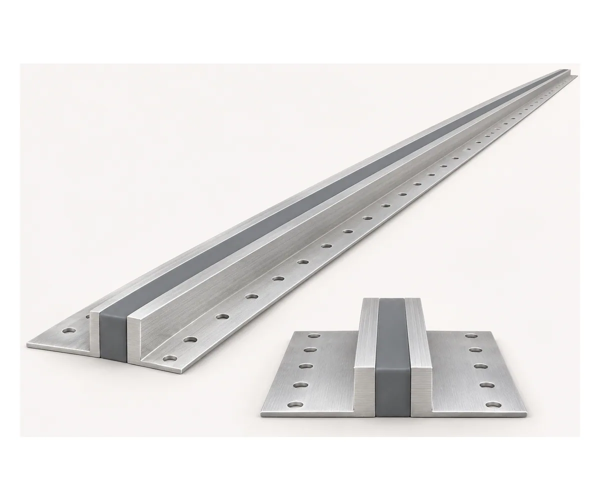 Aluminum Floor Movement-Joint Profiles with a Flexible Insert
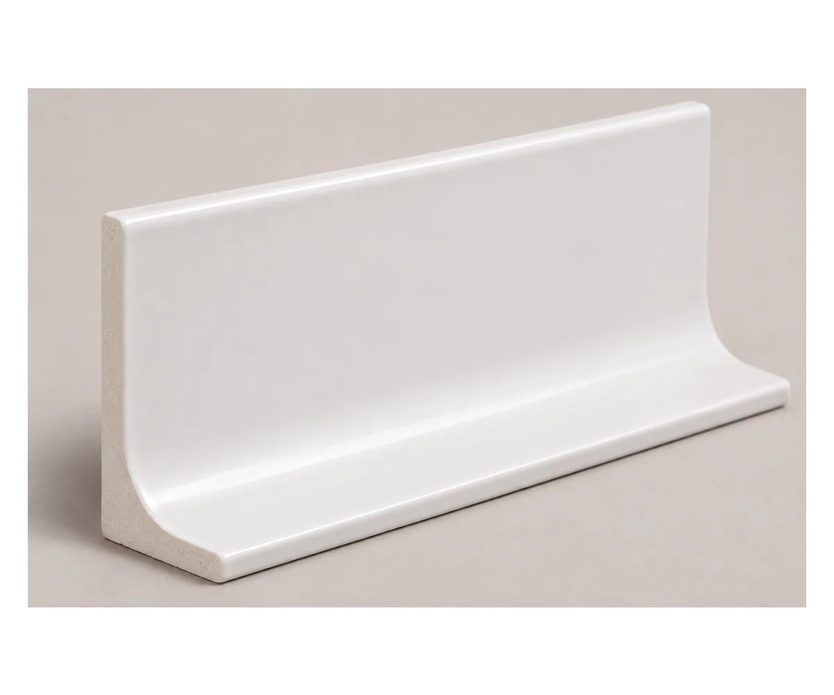 Ceramic Cove Base Tile with a Concave Floor Return
 35 mm Aluminum T-Molding for Same-Level Floor Transitions
 Flush Aluminum Stair Nosing for 10 mm Floor Finishes