2900 mm Main Board
The 2900 mm length covers 0.58 m² per uncut board at 200 mm installed width. Its 210 mm overall width and 12 mm section retain the same edge joint along the full length.
Wide Shiplap WPC Ceiling Boards
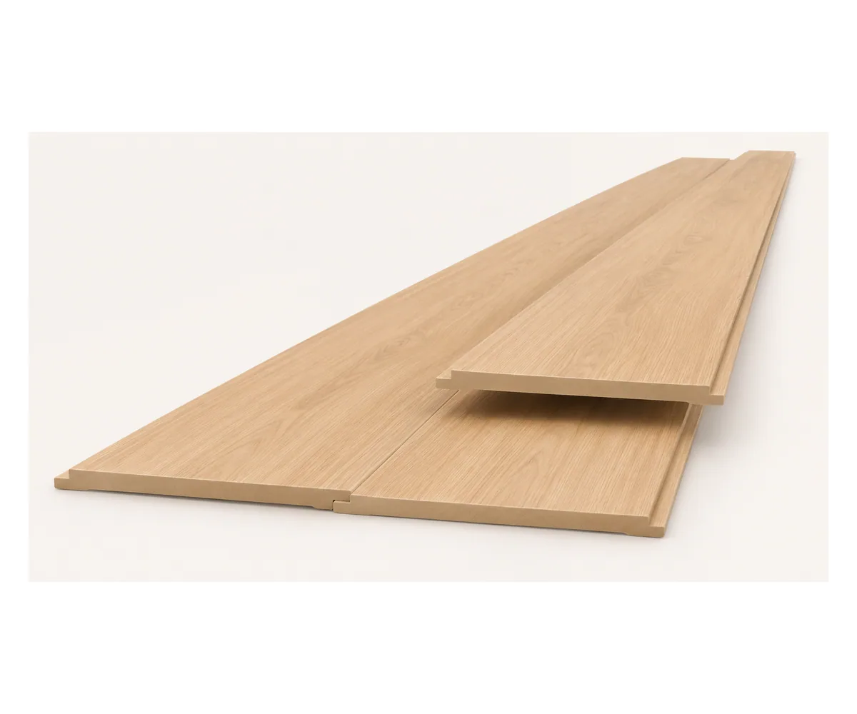
The wide board uses a solid wood-plastic composite section at 12 mm overall thickness. A light-oak decorative face runs along the continuous broad surface.
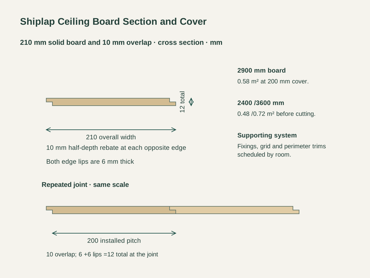
Both long edges have 10 mm-wide half-depth rebates on opposite faces. Each edge lip is 6 mm thick, so the overlapped joint returns to the same 12 mm total board thickness.
The 10 mm overlap reduces each 210 mm overall board width to 200 mm installed cover. Repeated boards make a continuous ceiling face with joints following the chosen board direction.
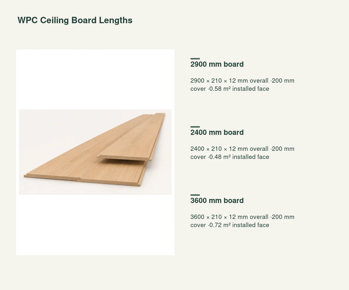
The 2900 mm length covers 0.58 m² per uncut board at 200 mm installed width. Its 210 mm overall width and 12 mm section retain the same edge joint along the full length.
The 2400 mm format covers 0.48 m² before cutting. It gives a shorter handling and joint-planning length while keeping the same light-oak face and half-depth rabbets.
The 3600 mm format covers 0.72 m² per uncut board. The ceiling plan locates its end joints, supports and service openings against the longer continuous run.
| Board material | Solid wood-plastic composite; light-oak decorative face |
|---|---|
| Length and installed area | 2900 × 210 × 12 mm overall ·200 mm cover ·0.58 m² installed face |
| Overall section | 210 W × 12 T mm |
| Installed cover width | 200 mm per repeated board |
| Long-edge joint | Opposite 10 mm-wide rabbets; 6 mm half-thickness lips |
| Joint thickness | 6 +6 =12 mm at the overlap |
| Ceiling interface | Board supports, fixings, perimeter allowance and service cutouts on ceiling detail |
| Supply unit | One shiplap board in the chosen length; support/trim package itemized by room |
 Open product drawing ↗
Count board rows from the 200 mm installed width; the 210 mm overall section includes the lap. The ceiling layout identifies cut rows, end joints, perimeter cuts and spare lengths.
The board schedule carries the supporting-ceiling system, fixing points, member spacing and attachment detail together. Board end joints and edge fixings meet the designed support positions.
The reflected ceiling plan locates lights, vents, access openings and wall junctions. Cutouts, perimeter allowance and matched trims follow the same ceiling and service detail.
List 2400, 2900 or 3600 mm lengths by ceiling area and row layout. Include cut lengths, end-joint positions and retained spare boards.
Quote the solid 12 mm WPC board, 210 mm overall width, 200 mm cover and 10 × 6 mm opposite rebates. Retain the light-oak face sample and exposed-edge treatment.
Schedule the supporting grid, fixings, perimeter trims, ends and service-opening treatments as itemized components. Their dimensions follow the ceiling layout and supporting construction.
Keep long boards supported and finished faces protected. Mark lengths, board counts, room references, trim bundles and destination on the packing list.
Each board is 210 mm wide overall. Its 10 mm shiplap overlap leaves 200 mm installed cover, which is the width used for repeated ceiling rows and area takeoff.
Opposite edges have 10 mm-wide, half-depth rabbets. The two 6 mm lips overlap, returning the joint to the 12 mm overall board thickness.
This configuration is a solid 12 mm WPC board with a broad continuous face. The light-oak surface and stepped long edges stay with the same wide-board reference.
At 200 mm cover, the 2400, 2900 and 3600 mm lengths provide 0.48, 0.58 and 0.72 m² per uncut board respectively. Cutting, perimeter rows and retained spares are counted on top.
The ceiling drawing locates supports, fixings, end joints, lights, vents and access openings. The board direction, cutouts, perimeter allowance and trims follow that reflected ceiling plan.
Include board lengths, row quantities, cutting and spare needs, face reference and exposed edges. List supports, fixings, trims, opening treatments, protected packing and destination as individual items.
 PVC-Faced Gypsum Lay-In Ceiling Tiles
 40 × 45 mm WPC Ceiling Strips with an Open Channel
 50 × 50 mm WPC Ceiling & Screen Strips
 60 × 70 mm WPC Ceiling Strips with a Laminated Surface