595 × 595 × 8 mm Square
The default square tile fits a 600 × 600 mm nominal grid module. Its actual face is 0.354025 m², while the grid module occupies 0.36 m² of the ceiling layout.
PVC-Faced Gypsum Lay-In Ceiling Tiles
The white PVC face gives the ceiling tile a fine, even texture and a wipeable finished surface. Its finish reference is kept with the ceiling layout so replacement panels follow the same face direction and appearance.
A gypsum core forms the tile body. A reflective metalized backing film covers the rear face, producing the silver-backed construction used with the PVC-finished front.
Straight square edges rest on the exposed T-grid flange. The panel lifts and tilts through the module for planned access to the ceiling cavity, with clearance coordinated above the removable tiles.

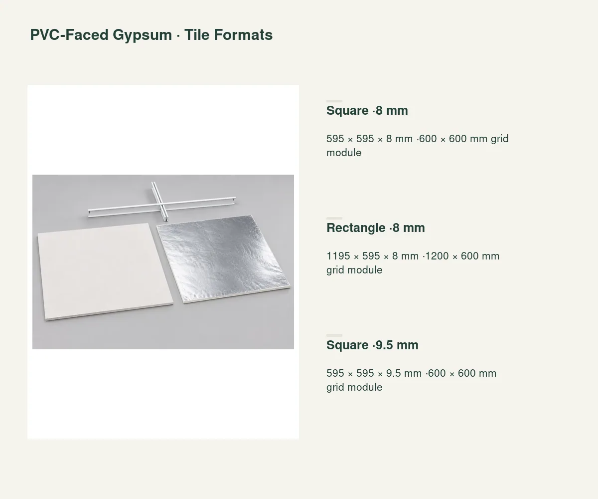
The default square tile fits a 600 × 600 mm nominal grid module. Its actual face is 0.354025 m², while the grid module occupies 0.36 m² of the ceiling layout.
The rectangular tile fits a 1200 × 600 mm nominal module. It creates a longer ceiling rhythm with 0.711025 m² of actual tile face in a 0.72 m² grid module.
The 9.5 mm square option retains the 600 mm grid module with a deeper tile body. Grid seating, perimeter height and adjacent ceiling components follow the chosen section.
| Panel construction | Gypsum core with white textured PVC face and reflective backing film |
|---|---|
| Ceiling tile format | 595 × 595 × 8 mm ·600 × 600 mm grid module |
| Square tile sections | 595 × 595 mm face in 8 mm or 9.5 mm overall thickness |
| Rectangular tile section | 1195 × 595 × 8 mm |
| Nominal grid modules | 600 × 600 mm square;1200 × 600 mm rectangle |
| Actual tile-face areas | Square 0.354025 m²; rectangle 0.711025 m² |
| Edge and support | Square lay-in edge on a 24 mm exposed T-grid flange |
| Supply unit | Individual panels by format/thickness; grid and suspension components itemized |
 Open product drawing ↗
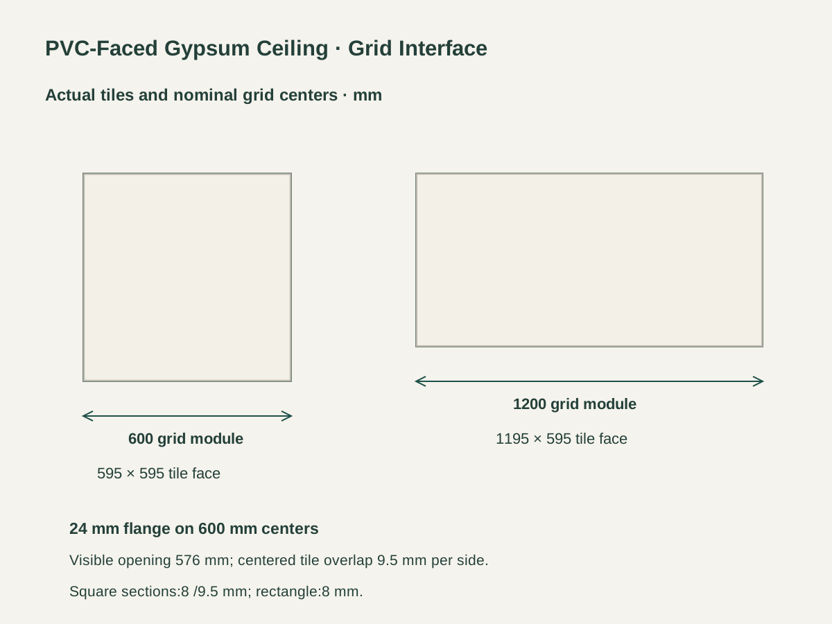
The ceiling design uses a 24 mm exposed T-grid flange. A 600 mm center module leaves a 576 mm clear opening, with the 595 mm tile overlapping the flange by 9.5 mm on each side when centered.
The reflected ceiling plan sets main runs, cross tees and cut borders from the room dimensions. Perimeter angles, suspension points and movement details are scheduled with the complete grid system.
Lights, diffusers and other service units receive dedicated structural supports. Their cutouts and access zones are coordinated with removable tiles and the lifting space above the grid.
List each tile size and thickness by room or ceiling zone. The grid layout counts full tiles, perimeter cuts and the separate replacement allowance.
Itemize main tees, cross tees, hangers and perimeter angles with their finish and module references. The supporting structure and connection details remain on the ceiling-system schedule.
Identify lighting and ventilation openings, dedicated supports, access locations and any special edge pieces. Their component quantities and installation responsibilities are assigned together.
Protect PVC faces and panel corners during packing. Labels distinguish tile thickness, square/rectangular format, room location and the retained replacement reference.
The panel uses a gypsum core, white textured PVC face and reflective metalized film on the back. The square lay-in edges sit on the exposed grid flange.
Choose 595 × 595 × 8 mm squares,1195 × 595 × 8 mm rectangles, or 595 × 595 × 9.5 mm squares. The square formats follow a 600 × 600 mm module; the rectangle follows 1200 × 600 mm.
The 600 mm dimension is the grid center spacing. With a 24 mm flange, the clear opening is 576 mm. A centered 595 mm tile bears over that opening with 9.5 mm of flange overlap at each side.
The 595 mm square tile has 0.354025 m² of face, and its 600 mm module has 0.36 m². The 1195 × 595 mm tile has 0.711025 m² of face in a 0.72 m² module. The ceiling layout counts tiles from the actual grid and perimeter cuts.
The square-edge panels lift and tilt out of their grid openings. Access positions and the clear lifting space are planned around ducts, pipes, cables and independently supported service units.
Include the reflected ceiling plan, tile format/thickness, finish and room quantities. Add grid and suspension components, perimeter details, service openings, access zones, replacement tiles and destination.
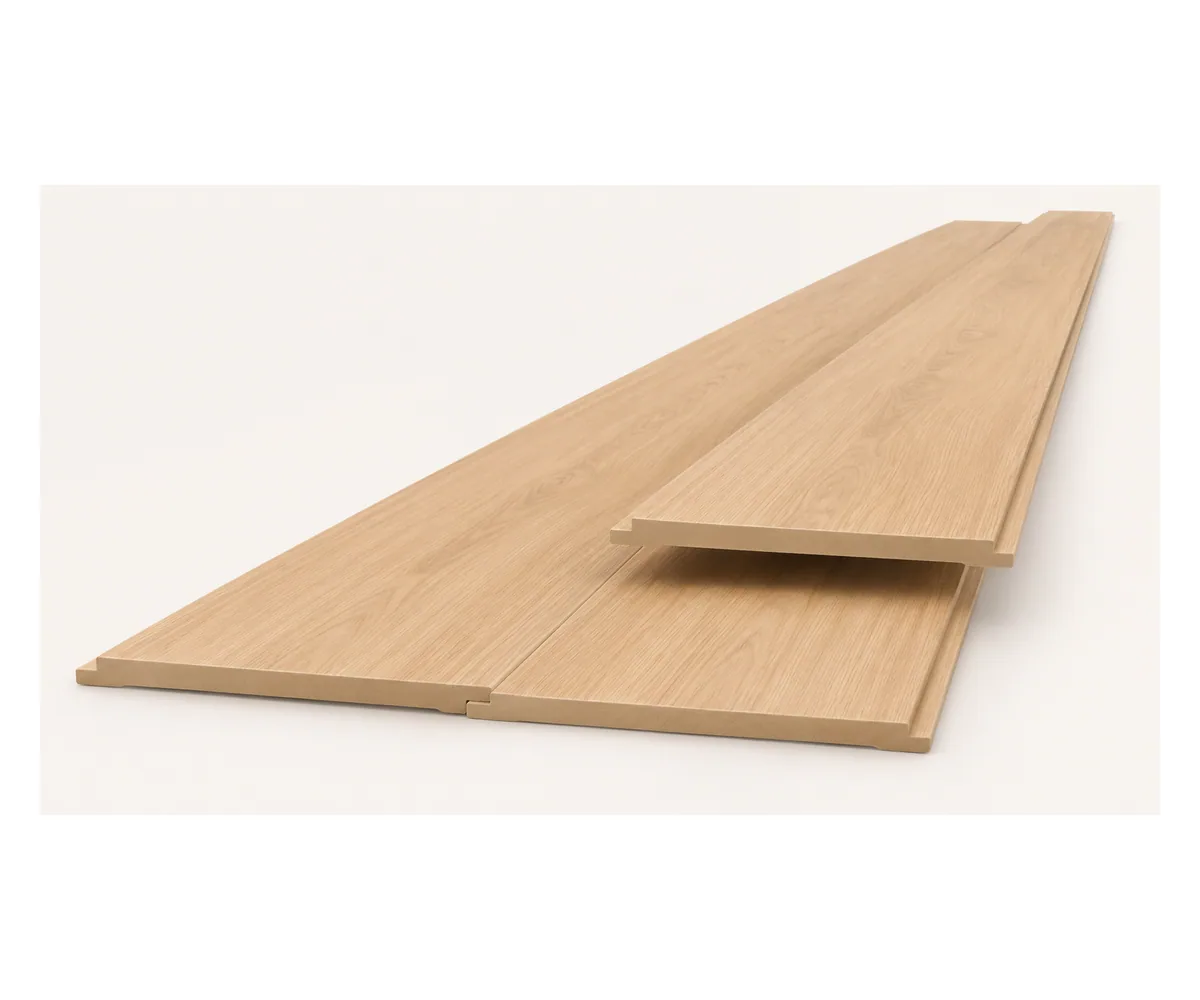 Wide Shiplap WPC Ceiling Boards
 40 × 45 mm WPC Ceiling Strips with an Open Channel
 50 × 50 mm WPC Ceiling & Screen Strips
 60 × 70 mm WPC Ceiling Strips with a Laminated Surface