Four-Module Main Package
The main package contains four matching body-spray fittings. The shower elevation marks each position and its connection to the manifold, which has its own schedule line.
Adjustable Shower Body-Spray Jet Sets
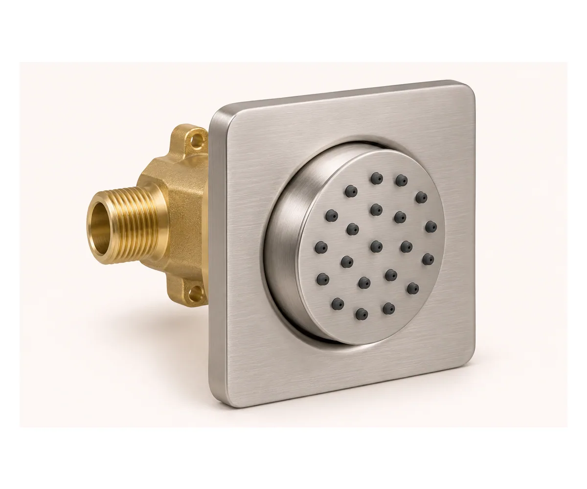
An 80 × 80 mm brushed 304 stainless trim frames the body-spray fitting, with the square face, wall seal and finish on one component reference for the shower elevation.
A 55 mm round face sits in the adjustable center. Silicone nozzles follow the selected face pattern, while the pivot and sealing arrangement allow the spray direction to be set within the final module detail.
A brass inlet body carries the G1/2 threaded connection behind the wall trim. The rear body-depth basis is 55 mm, with 15 mm front projection referenced from the finished-wall plane.
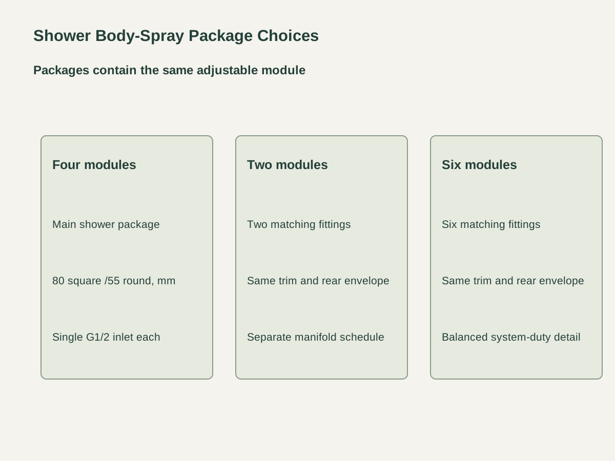
The main package contains four matching body-spray fittings. The shower elevation marks each position and its connection to the manifold, which has its own schedule line.
A two-module package keeps the same 80 mm trim, 55 mm round face and rear connection envelope. Each fitting has its own inlet body, seal and directional face.
The six-module package increases the count within the same component design. Pipe branches, valve duty and balancing requirements follow the complete shower-system schedule.
| Face trim | 80 ×80 mm brushed 304 stainless square |
|---|---|
| Body-spray package | Four 80 mm-square modules ·55 mm round face ·G1/2 inlet each |
| Nozzle face | 55 mm round adjustable face with silicone nozzles |
| Front projection basis | 15 mm from finished-wall plane |
| Rear body-depth basis | 55 mm behind finished-wall plane |
| Inlet interface | Single brass G1/2 threaded inlet per module |
| System interface | Module positions, manifold, pipe sizing and balanced hydraulic duty by shower design |
| Supply unit | Matching module package; each unit includes inlet body, trim, seal and adjustable nozzle |
 Open product drawing ↗
The shower drawing identifies module centers, finished wall planes and intended spray directions. Adjacent controls, wall corners and user positions are coordinated with those points.
The wall section reserves the 55 mm rear-body basis and the inlet connection space. Pipe support, wall seals, service access and substrate openings follow the actual module construction.
The hydraulic design establishes pipe size, available pressure, flow balance and valve duty for the chosen module count. The project manifold, mixer and supply arrangement are itemized with the shower system.
Count two-, four- or six-module packages by shower number. Keep each component position and inlet reference against the matching elevation.
Quote 80 mm brushed stainless trim, 55 mm round face, silicone nozzles, brass inlet and the directional pivot/seal detail. The accepted finish and component sample remain paired.
Schedule the G1/2 connections, branch/manifold layout, wall support and sealing parts. The mixer, pipework and required hydraulic duty use separate system order lines.
Protect trim faces, nozzles and threads. Bundle each module package with its seals and position labels, with counts and destination on the packing list.
The square trim is 80 ×80 mm and contains a 55 mm round directional spray face. The brushed stainless surface and silicone nozzle pattern follow the component reference.
Choose two, four or six matching modules per package. Each fitting retains the same trim, round face, inlet and envelope basis.
The 15 mm front projection starts at the finished-wall plane. The wall section pairs that datum with the trim, seal and adjustable face.
The rear body-depth basis is 55 mm behind the finished wall, with one brass G1/2 inlet per fitting. The actual pipe connection, support and service space follow the module detail.
The shower-system design establishes pipe size, available pressure, valve duty and balanced flow for the selected module count. The manifold and mixer are scheduled with that complete system.
Each fitting includes its inlet body, trim, seal and adjustable nozzle. The package adds position labels and protective packing; manifolds, mixers and pipework have separate system quantities.
 Hand Shower Slide-Bar Kits with Adjustable Holders
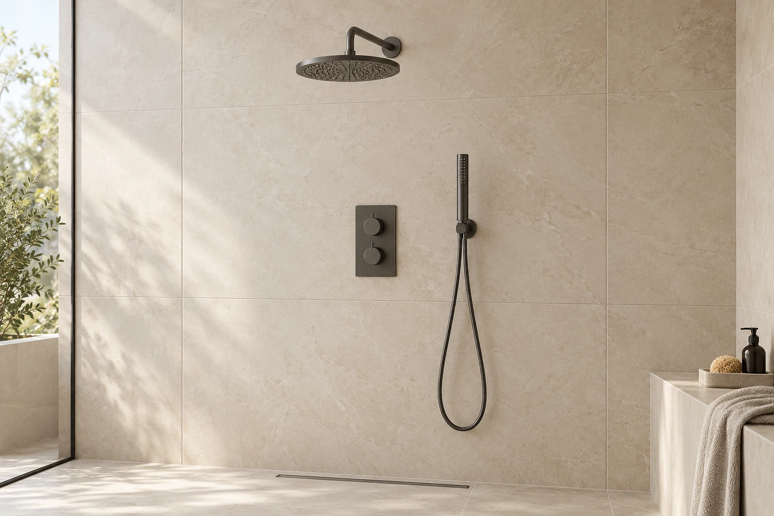 Concealed Shower Systems with Rain & Waterfall Outlets
 Surface-Mounted Stainless Steel Shower Panels
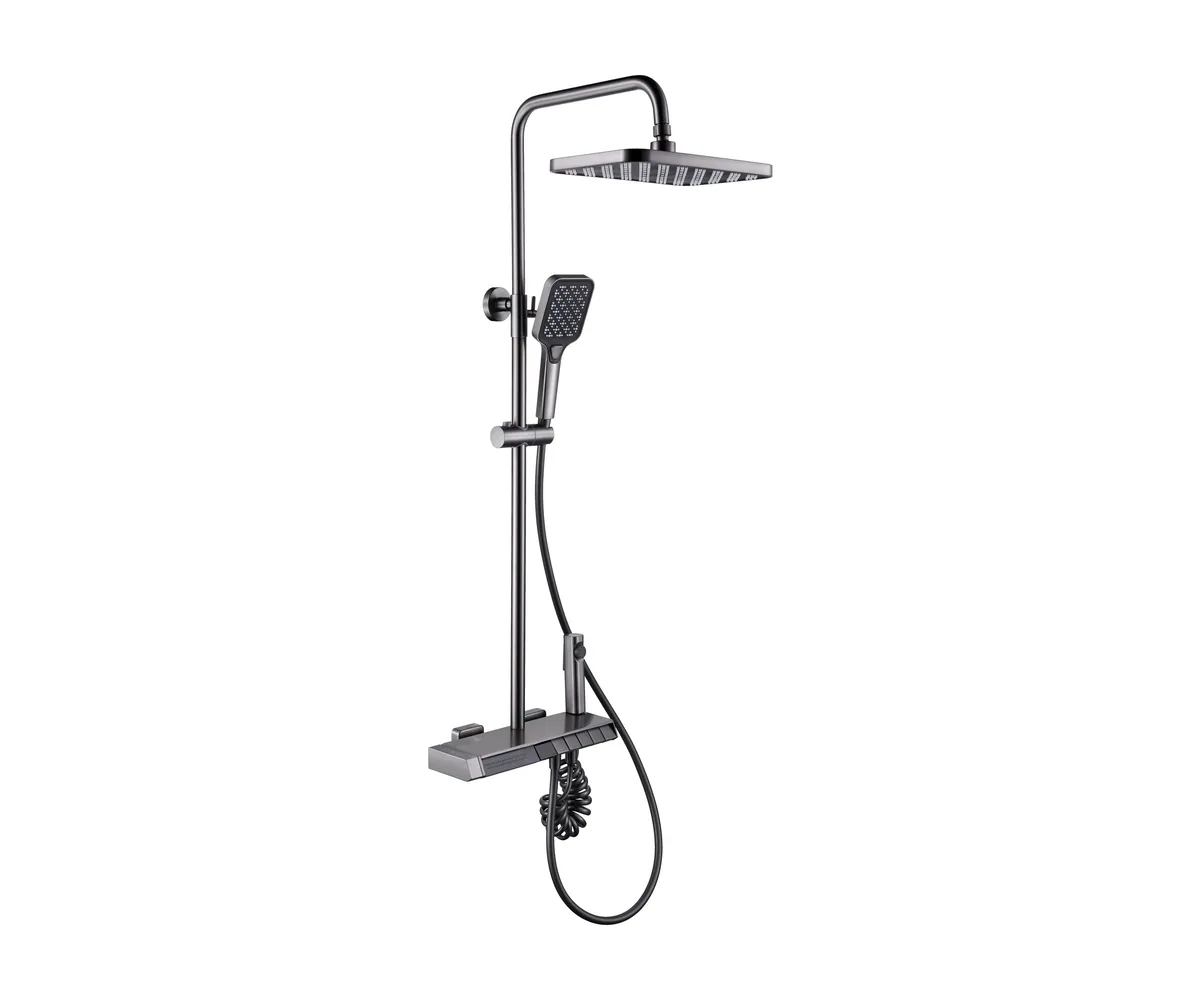 8018 Push-Button Thermostatic Shower Set