On this page
Measure the room for the new cabinet plan: establish reference points, record walls and openings, locate services and obstructions, then check that complete dimension chains agree. Release a clearly labeled measurement revision for an initial quotation only after contradictions are resolved. Production requires the project’s final survey and approved drawings; an existing cabinet’s width is context, not proof of the available wall.
This step-by-step checklist produces a usable quote-input record. The filled R-50 example includes a 20 mm recording conflict, its assumed remeasurement and a completed release decision.
Step 1. Set the scope, units and reference points
Input: the room, intended project scope, a sketch and an agreed measuring method. Record the date, measurer, tools and whether the surfaces are existing or proposed.
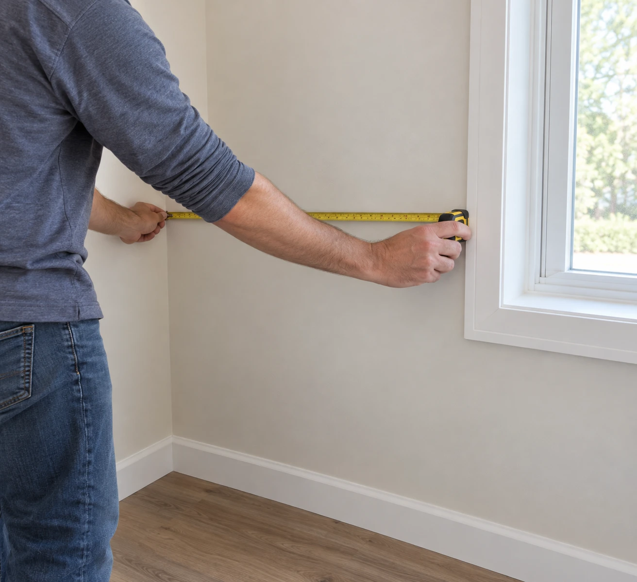
Action: label every wall and state the viewing direction. Choose one unit throughout. Record the tool’s reference method: if a tape housing forms an endpoint, account for its length using that tool’s instructions rather than treating the exposed blade reading as the whole span. Establish a retained vertical benchmark and define how horizontal positions are recorded. In R-50, all dimensions are millimeters. Each wall elevation is viewed straight on from inside the room; its local x starts at the left finished corner and increases rightward. All z elevations use the same retained finished-floor mark at the northwest corner as z = 0.
Exception and output: if flooring or wall finishes will change, distinguish the current face from the proposed finished face. Do not silently subtract an assumed tile or plaster thickness. The completed output is a record header that lets another person interpret every number.
Step 2. Sketch and measure the room boundary
Input: the labeled sketch and accessible finished wall faces. Mark recesses, returns, columns and inaccessible areas before recording lengths.
Action: measure each wall at identified heights and retain the separate readings. Record the exact endpoints. Home Depot Canada’s measuring guide calls for wall measurements at different heights; the important procurement result is that variation remains visible. Opposite walls do not have to be forced into equal dimensions, and four lengths alone do not prove right-angle corners.
Exception and output: when a cabinet, pipe or other obstruction prevents a direct reading, mark the span unmeasured and explain the obstruction. Do not use the existing cabinet frontage as a substitute. Output a dimensioned boundary sketch, including any unresolved geometry and the heights at which readings were taken.
Step 3. Locate openings and their full trim envelopes
Input: each window, doorway and surrounding trim or casing. Identify which physical edges the drawing uses.
Action: record the corner-to-trim distance, full trim width and remaining distance to the other corner on the same horizontal line. Record bottom and top elevations, projections and the opening’s movement into the room. The Home Decorators Collection guide uses this corner/opening/opposite-corner sequence; IKEA’s self-measuring guidance also includes the space needed to open doors and windows.
Exception and output: a corner-to-opening segment plus opening width is only a partial chain if the remaining wall span is missing. It cannot be called a wall closure. Keep clear-opening, frame and outer-trim dimensions distinct. Output an opening record tied to a wall, datum, view and photograph.

Step 4. Record vertical space and fixed obstructions
Input: the retained floor benchmark, ceiling and visible soffits, beams, skirting and other projections.
Action: record floor and ceiling elevations at named positions against the same benchmark. Show obstruction width, depth/projection and bottom/top elevations. If a floor rises toward one corner, retain that observation rather than applying one floor-to-ceiling measurement everywhere.
Exception and output: distinguish a ceiling elevation from a local clear height. A ceiling at z = 2,434 above the benchmark and a local floor at z = 3 give 2,431 of local clearance, not 2,434. Output a vertical constraint record; the designer and installer determine its effect on cabinet setting and fit.
Step 5. Locate service points and their physical extent
Input: accessible water, waste, electrical, gas and ventilation features. Record what is visible and have relevant trades identify uncertain services.
Action: give each point an ID, wall reference, x and z coordinate, location convention and projection. State whether a number is a pipe center, plate center or an opening edge. Add the actual size or bounding extent needed to identify the feature; a center point alone does not describe the space it occupies. IKEA’s guidance requests service locations relative to floors and walls.
Exception and output: concealed or unidentified services remain explicitly unverified. Proposed relocations receive a separate status and responsible person. Output a service map, not permission to move or disconnect anything and not a completed cabinet cutout design.
Step 6. Attach product references and check the finish assumptions
Input: retained or proposed appliance/sink references, the finish schedule and photographs of the room.
Action: mark what stays, what is removed and what changes. Attach actual installation documents for products that affect the cabinet design. Keep existing appliance measurements as existing-condition records; a replacement product needs its own model-specific information. Confirm whether the measured floor and wall faces will remain the finished faces.
Exception and output: an undecided appliance or unknown finish build-up is a stated quotation assumption, not a guessed dimension. Output a linked reference list and change log. This step collects inputs; it does not select a kitchen layout or reproduce appliance installation clearances.

Step 7. Reconcile complete chains and remeasure conflicts
Input: overall wall readings and their complete segment chains, using identical endpoints, height and face.
Action: add the segments and compare them with the independently recorded overall span. If they differ, check the source entry, unit, endpoint and physical reading. Repeat the relevant measurement; keep the original value in the revision history. Averaging unrelated readings can hide the problem.
Exception and output: do not apply a global acceptable-error threshold from a tutorial. The project’s responsible parties agree the required method and acceptance criteria. R-50 below corrects a demonstrated entry error, rather than claiming that any difference under a chosen number is acceptable. Output a resolved conflict log or an explicit quotation limitation.
Step 8. Release a named revision for its permitted purpose
Input: the checked record, photographs, product references, remaining qualifications and the planner’s response.
Action: complete these release fields:
- Identify the revision accepted for an initial quotation and its accompanying assumptions.
- Keep the original readings, correction and acknowledgment together.
- Confirm who performs the final production survey and when it occurs relative to completed surfaces and service changes.
Exception and output: a quote-input release does not authorize manufacture. Unverified final geometry, installation details or changed surfaces must be resolved through the project’s final survey and drawing process. Output a dated release record with a clear purpose, not an unlabeled sketch that can be mistaken for a cutting instruction.
Record the finished corner and outer trim as reference surfaces, accounting for the tape case when it forms an endpoint.

R-50: a filled room record with a corrected conflict
R-50 records an existing empty kitchen for an initial cabinet quotation. The wall labels N/E/S/W are sketch identifiers, not a certified rectangular plan. Each x is local to its wall as defined in Step 1. Vertical readings share the northwest retained-floor benchmark; they are not all measured from the floor immediately below the feature.
| Record | Filled observation | Status / interpretation |
|---|---|---|
| Survey header | R-50; October 30, 2026; measurer A; tape and level/laser method recorded; photos P1–P6. | Observations and responses recorded. Rev B is for initial quotation only. |
| N wall | Finished-corner to finished-corner: 3,240 at z150; 3,236 at z900; 3,232 at z2100. | Three separate horizontal spans. Do not mix them in one closure or average them into a fabrication length. |
| Other walls | E: 2,800; S: 3,242; W: 2,804, each at z900 between its own finished corners. | Recorded independently. Corner angles, diagonals and wall bow remain for final survey; no rectangle is inferred. |
| N window | At z900, full trim chain after recheck: left span 600 + trim width 1,200 + right span 1,436 = 3,236. Trim bottom z800; top z2000. | All chain endpoints lie on the same z900 line and use the same finished-face reference. Trim projection into room: 20. |
| E doorway | Facing E from the room, x starts at its left/north corner. At z900: 500 + full trim width 900 + remaining span 1,400 = 2,800. | Complete E-wall chain. Trim bottom z2 at the recorded doorway floor; top z2100. The existing door swings away from this room, documented in P4. |
| N water / waste | Visible centers: hot x2150/z550; cold x2250/z550; waste x2200/z450. Pipe projection envelope: 80 from N finished face. | Existing positions retained for quotation; trade verification of connection type/size and cabinet interfaces remains required. |
| N electrical / vent | Outlet plate center x2500/z1100; plate envelope 80 × 80, projection 15. Vent center x2700/z2200; visible opening diameter 150. | Existing visible locations, not electrical/gas certification or an appliance connection design. No visible gas point recorded; concealed services unverified. |
| Vertical map | NW floor z0, ceiling z2440. SE floor z3, ceiling z2434; SE local clearance = 2,434 − 3 = 2,431. | Both ceiling readings are elevations from the same NW benchmark. No ceiling height is assumed uniform throughout the room. |
| Finished faces | Assumed owner/contractor reply: existing tile floor and painted wall faces remain; no new overlay or wall build-up in this quote. | Finish assumption confirmed for Rev B. Any change triggers a revised record and quotation review. |
The conflict: Rev A entered the N left span as 620. Its full chain was 620 + 1,200 + 1,436 = 3,256, which exceeded the independently recorded z900 wall span of 3,236 by 20. This was a full-wall comparison, not an incomplete chain being made to “close.”
The correction: assume a return measurement checks the same finished corner, outer trim edges and z900 line. It confirms the left span as 600, with the other readings unchanged. The measurer identifies the 620 entry as a transcription error, retains it in the log and issues Rev B. The corrected chain totals 3,236 and has zero arithmetic residual against that recorded overall span. Zero residual alone is not proof of survey accuracy.

The completed decision: assume the planner acknowledges the corrected chain, service-location status, independent wall readings and retained-finish response. The buyer releases R-50 Rev B for the initial quotation and rejects Rev A for further use. The quotation records final geometry, service-interface verification and production survey as separate release conditions. No cabinet width, filler, layout or cutting size is approved by this example.
Copy these fields into the measurement record
Use one feature row per wall segment, opening or service. Keep the reference convention with the numbers when the record is copied into another document.
Project / room / revision:
Date / measurer / tool method:
Purpose: quotation or final survey:
Units / wall ID / viewing direction:
Horizontal datum and x direction:
Vertical benchmark and z datum:
Measured current face / proposed face:
Feature ID / photo or drawing reference:
Endpoint or center convention:
x start / x end / width:
z bottom / z top or center:
Depth or projection / size envelope:
Overall span / full-chain sum:
Difference / recheck result / reason:
Existing / retained / proposed / unknown:
Responsible verifier / response date:
Accepted revision / permitted use:
Remaining final-release conditions:
Send NOVARMIA the labeled plan, wall elevations, service map, photographs and revision log for an initial cabinet discussion. Include the intended quotation assumptions and the person responsible for the final survey so measurements retain their meaning through the handoff.
FAQ
Can a phone scan replace the measurement record?
It can support a project if the responsible planner accepts the method and verifies the relevant dimensions. Preserve datums, endpoints, inaccessible areas and revision status. A convenient 3D view does not by itself provide those acceptance records.
What if trim will be removed before the new cabinets arrive?
Record the existing trim envelope and the proposed removal separately. Obtain confirmation of the resulting finished face and repair scope. Do not erase the existing condition before the change is accepted and measured.
Should hidden wall construction be guessed from a visible surface?
No. Record what is observed and assign verification to the responsible installer or trade where fixing or concealed services matter. A painted wall measurement does not identify its construction or fixing capacity.
Can a countertop be ordered from the cabinet quotation sketch?
Only through the countertop supplier’s accepted process and required survey/template stage. Cabinet quotation measurements do not automatically establish final top dimensions, cutouts or installation conditions.